
Welding jig and welding production line

A welding jig and clamp body technology, applied in welding equipment, auxiliary welding equipment, welding/cutting auxiliary equipment, etc., can solve the problems of low processing efficiency of parts, hidden safety hazards, personal injury of operators, etc., and achieve the goal of improving processing efficiency. Effect

Active Publication Date: 2014-11-12
ANHUI JIANGHUAI AUTOMOBILE GRP CORP LTD
View PDF6 Cites 6 Cited by
  • Summary
  • Abstract
  • Description
  • Claims
  • Application Information

AI Technical Summary

Problems solved by technology

Obviously, in this way, loading and welding must be carried out in sequence, resulting in low processing efficiency of parts
[0004] In addition, in the above technology, the position where the operator performs the loading operation is the same as the position where the welding operation is performed. When the operator performs the loading operation, the welding device at this position is likely to cause personal injury to the operator, so that the entire welding process has Bigger security risk

Method used


Image

  • Welding jig and welding production line
  • Welding jig and welding production line
  • Welding jig and welding production line

Examples


Embodiment Construction

[0030] The core of the present invention is to provide a welding jig, which can improve the processing efficiency of components. Another core of the present invention is to provide a welding production line including the above-mentioned welding jig.

[0031] In order to enable those skilled in the art to better understand the technical solutions of the present invention, the present invention will be further described in detail below in conjunction with the accompanying drawings.

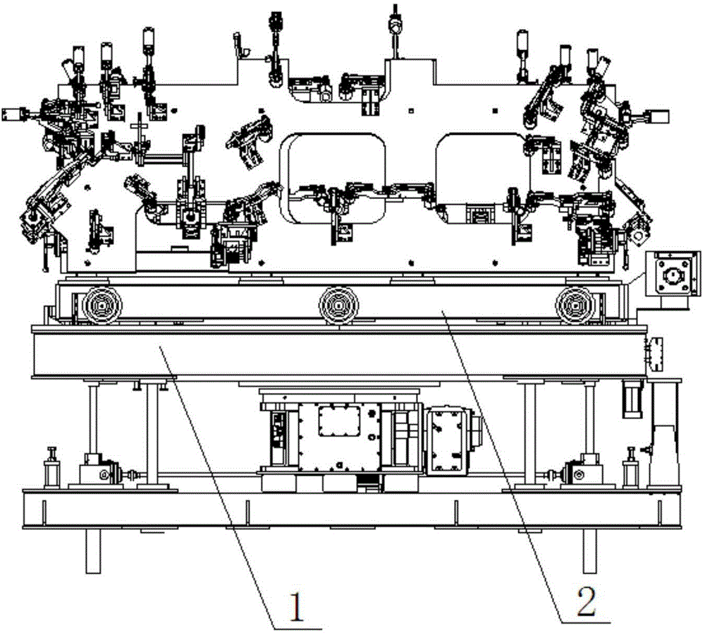
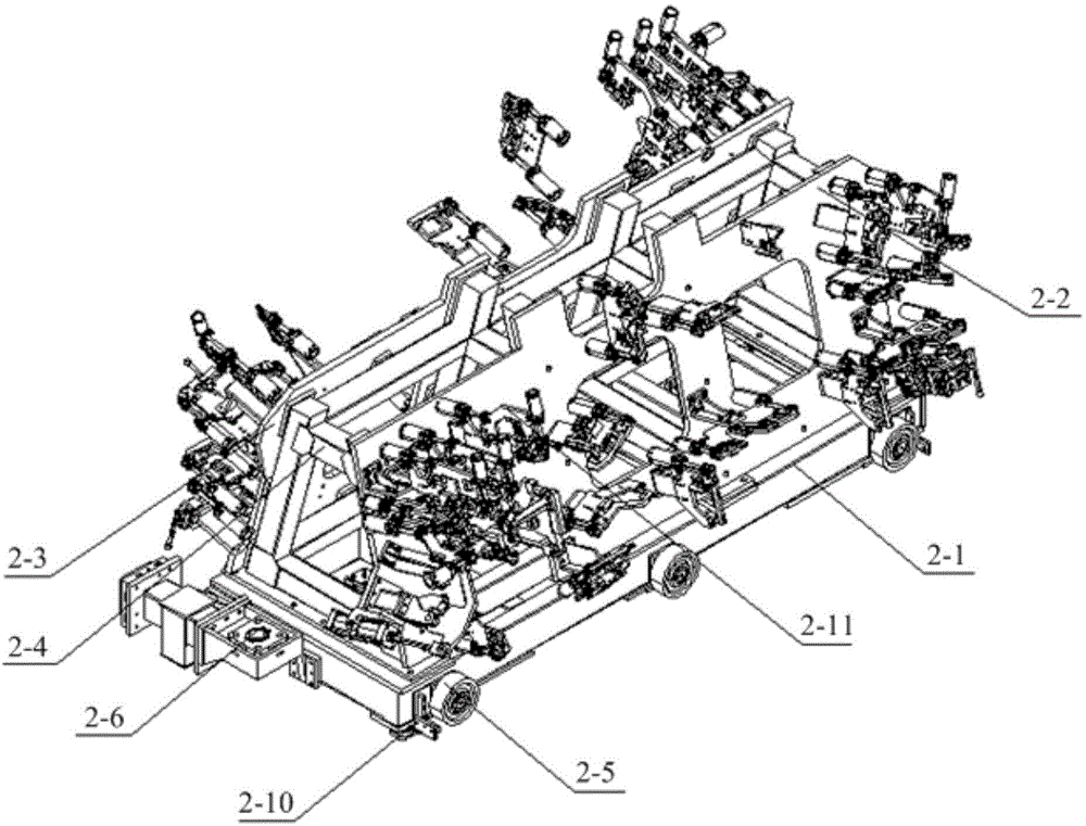
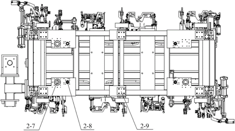
[0032] Such as Figure 1-6 As shown, the welding fixture provided by the embodiment of the present invention includes an installation base 1 and a clamp body 2. The installation base 1 is the installation basis of the entire welding fixture, which can be fixed on the working platform, and the clamp body 2 is used for positioning Processed workpieces to facilitate welding operations. The clamp body 2 is rotatably connected with the installation base 1, and the rotation axis of the clamp body 2 can ...


PUM


Abstract

The invention discloses a welding jig. The welding jig comprises an installation base (1), and also comprises a jig body (2) rotatably connected with the installation base (1), wherein the jig body (2) is provided with a workpiece feeding station, a welding station and at least two workpiece locating surfaces, and the same workpiece locating surfaces have switching strokes between the workpiece feeding station and the welding station. According to the welding jig, the jig body is provided with the at least two workpiece locating surfaces, so that the whole jig body can rotate, and workpieces can be welded while the workpieces are fed. Apparently, the welding jig can improve the processing efficiency of parts. The invention also discloses a welding production line.

Description

technical field [0001] The invention relates to the technical field of welding devices, in particular to a welding fixture. The invention also relates to a welding production line. Background technique [0002] Welding fixtures are widely used in the processing of parts, and their structure has a crucial influence on the processing quality and processing efficiency of parts. With the continuous improvement of people's requirements for processing quality and processing efficiency of parts, welding The performance of fixtures has received more attention. [0003] In traditional techniques, parts are positioned on welding fixtures before the welding operation takes place. During the specific operation, the operator needs to perform the loading operation in the area where the welding fixture is installed, and then perform welding after the loading is completed, and then proceed to the loading operation of the next component after the welding is completed. Obviously, in this w...

Claims


Application Information

Patent Timeline
Patent Type & Authority Applications(China)
IPC IPC(8): B23K37/04B23K37/00
CPCB23K37/0435B23K37/0461
Inventor 杜坤陈素平张丽芳吴卫枫
Owner ANHUI JIANGHUAI AUTOMOBILE GRP CORP LTD
Learn More