A welding equipment for large gas regulating valve

A technology for gas adjustment and welding equipment, applied in welding equipment, welding equipment, auxiliary welding equipment, etc., can solve the problems of inability to locate the flange, large flange volume, inconvenient flange adjustment, etc., to achieve continuous welding operation and reduce processing. Difficulty, the effect of reducing production costs

Active Publication Date: 2022-07-01
ZHEJIANG CHUNHUI INTELLIGENT CONTROL
View PDF0 Cites 0 Cited by
  • Summary
  • Abstract
  • Description
  • Claims
  • Application Information

AI Technical Summary

Problems solved by technology

[0003] Large-scale gas control valves need to weld flanges on both ends of the valve body during the processing process. The flange holes need to be positioned during welding to ensure that the flanges are welded on the valve body at the specified position. Due to the huge valve body, The volume of the corresponding flange is also large, it is very inconvenient to adjust the flange, and it is impossible to position the flange

Method used


Image

  • A welding equipment for large gas regulating valve
  • A welding equipment for large gas regulating valve
  • A welding equipment for large gas regulating valve

Examples


Embodiment Construction

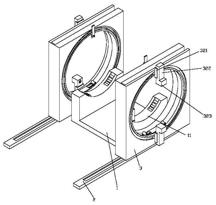
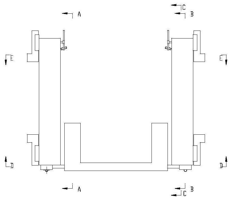
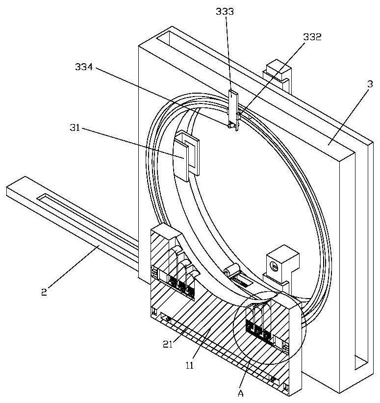
[0044] like Figure 1-28 As shown in the figure, a welding equipment for a large gas regulating valve includes a base plate 1, a support base 11 arranged on the base plate 1, and a material carrier frame 3 arranged on both sides of the base plate 1. There is a first material loading slot, a first movable slot is arranged on the side wall of the upper side of the loading frame 3, and two sets of first movable blocks 32 are arranged in the first movable slot. 32 is provided with a first connecting block 323, the first connecting block 323 is provided with a second movable groove, the second movable groove is provided with a first connecting rod 324, and one end of the first connecting rod 324 is provided with A first connecting spring 3241, the first connecting block 323 is provided with a motor 327 for driving the first connecting rod 324 to move in the second movable groove; A sixteenth movable slot is provided, a movable ring 33 is arranged in the sixteenth movable slot, and...


PUM


Abstract

The invention discloses a welding equipment for a large gas regulating valve, comprising a bottom plate, a support seat arranged on the bottom plate, and a material carrier frame arranged on both sides of the bottom plate, and a first carrier frame is arranged on the material carrier frame A material trough, a first movable trough is arranged on the upper side wall of the material carrier frame, two sets of first movable blocks are arranged in the first movable trough, and a first connection block is arranged on the first movable block , the first connecting block is provided with a second movable groove, the second movable groove is provided with a first connecting rod, one end of the first connecting rod is provided with a first connecting spring, and the first connecting block is There is a motor for driving the first connecting rod to move in the second movable slot; a sixteenth movable slot is arranged on the side wall of the other side of the material carrier frame, and the sixteenth movable slot is provided with There is a movable ring, and a welding torch is arranged on the movable ring; the first movable groove and the sixteenth movable groove are both annular structures.

Description

technical field [0001] The invention belongs to the technical field of valve body processing, and in particular relates to a welding device for a large gas regulating valve. Background technique [0002] The gas pressure regulator is commonly known as the pressure reducing valve, also known as the gas pressure regulating valve, which is a device that automatically changes the gas flow through the regulating valve to keep the outlet gas at the specified pressure. It is usually divided into two types: direct-acting and indirect-acting. [0003] Large gas control valves need to weld flanges on both ends of the valve body during processing. The flanges need to be positioned on the flange holes during welding to ensure that the flanges are welded on the valve body at the specified position. Due to the huge valve body, The corresponding flange volume is also large, which is very inconvenient to adjust with the flange, and at the same time it is impossible to position the flange. ...

Claims


Application Information

Patent Timeline
Patent Type & Authority Patents(China)
IPC IPC(8): B23K31/02B23K37/00B23K37/04B23K37/02
CPCB23K31/02B23K37/00B23K37/0435B23K37/0252
Inventor 贝正海朱杭军徐龙阮少烽戴葛峰章鹏飞钱灿荣陈春林黄雅芳
Owner ZHEJIANG CHUNHUI INTELLIGENT CONTROL
Why Eureka
Try Eureka