Automotive suspension assembly

An automobile suspension and assembly technology, applied in the direction of springs, leaf springs, springs/shock absorbers, etc., can solve the problems of destroying the mechanical properties of composite material leaf springs, insufficient research on installation structures, and great process difficulties, etc., to achieve guaranteed Improvement of maneuverability, lateral flexibility, and increased stiffness of leaf springs

Active Publication Date: 2014-11-19
ANHUI JIANGHUAI AUTOMOBILE GRP CORP LTD
View PDF7 Cites 4 Cited by
  • Summary
  • Abstract
  • Description
  • Claims
  • Application Information

AI Technical Summary

Problems solved by technology

[0009] However, the excellent performance obtained by composite leaf springs mainly depends on the improvement of the material itself, and the research on the mounting structure is insufficient
In fact, when the leaf spring is installed, the general leaf spring is installed on the frame by means of the coil ears at both ends, as stated in the Chinese utility model patent of application number: 201220646204.9, invention name: "automotive leaf spring" Publicly, for composite leaf springs, it is very difficult to form roll lugs at both ends, and punching holes will destroy the mechanical properties of composite leaf springs

Method used


Image

  • Automotive suspension assembly
  • Automotive suspension assembly
  • Automotive suspension assembly

Examples


Embodiment Construction

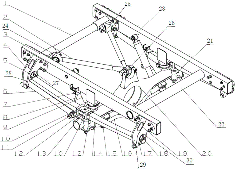
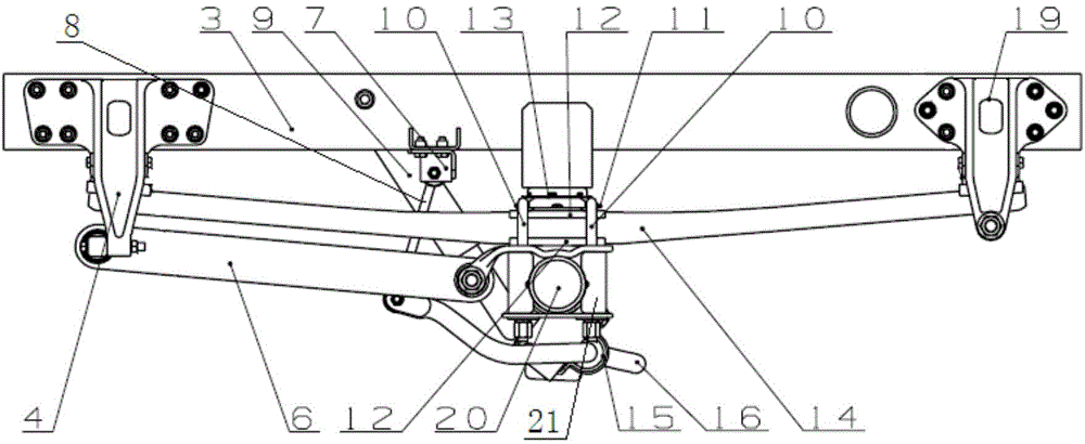
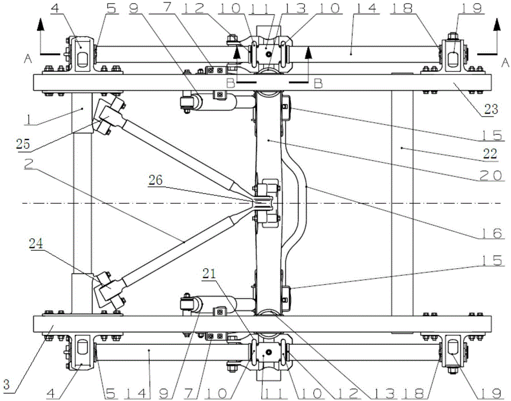
[0041] combine Figure 1 to Figure 5 . In the automobile suspension assembly of this embodiment, the front beam 1 , the rear beam 22 , the left longitudinal beam 3 and the right longitudinal beam 23 are connected together to form a frame-type vehicle frame. Since the components installed on the left longitudinal beam 3 and the right longitudinal beam 23 are basically symmetrical in structure, only the structure installed on the left longitudinal beam 3 is used as an example for description. A front leaf spring support 4 and a rear leaf spring support 19 are installed on the longitudinal beam 3 . from Figure 4 It can be seen more clearly that the front leaf spring support 4 has a first leg 27 and a second leg 28 between which the front end of the composite leaf spring 14 is inserted. from Figure 5 It can be seen more clearly that the rear leaf spring bracket 19 has a third leg 29 and a fourth leg 30, and the rear end of the composite material leaf spring 14 is inserted be...


PUM


Abstract

The invention provides an automotive suspension assembly which comprises an automotive frame and a composite leaf spring. The automotive frame is provided with a transverse beam and a longitudinal beam. The composite leaf spring is installed on a front leaf spring support and a rear leaf spring support on the longitudinal beam. The front leaf spring support and the rear leaf spring support are respectively provided with two supporting legs. The front end of the composite leaf spring is inserted between the two supporting legs of the front leaf spring support. The rear end of the composite leaf spring is inserted between the two supporting legs of the rear leaf spring support. A soft sliding block is arranged between the upper end face of the front end of the composite leaf spring and the front leaf spring support. A soft sliding block is arranged between the upper end face of the rear end of the composite leaf spring and the rear leaf spring support. A roller making contact with the lower end face of the rear end of the composite leaf spring is arranged between the two supporting legs of the rear leaf spring support. According to the automotive suspension assembly, no spring eyes need to be machined on the composite leaf spring, the technological difficulty is low, and smoothness is good.

Description

technical field [0001] The invention relates to the field of automobile chassis, in particular to an automobile suspension assembly. Background technique [0002] With the improvement of roads, customers have higher and higher requirements for ride comfort and comfort, and higher requirements for the protection of transported high-end goods. At the same time, customers have higher and higher requirements for the reliability of chassis components. , At the same time, it is also required to reduce the cost of using the whole vehicle. [0003] At present, the rear suspensions of commercial vehicles mainly include leaf spring rear suspension and air spring rear suspension. The frame adopts variable cross-section leaf spring suspension, and the vehicle with higher requirements for ride comfort adopts air spring suspension. [0004] The existing leaf spring rear suspension mechanism is widely used in various commercial vehicle rear suspensions due to its simple structure, low un...

Claims


Application Information

Patent Timeline
IPC IPC(8): B60G11/10
Inventor 刘守银
Owner ANHUI JIANGHUAI AUTOMOBILE GRP CORP LTD
Why Eureka
Try Eureka