
Control room for hoisting equipment

A lifting equipment and control room technology, applied in the field of lifting equipment, can solve the problems of easy occurrence of unsafe, inconvenient observation of the situation above and below the lifting goods, and achieve the effect of increasing the scope of vision

Inactive Publication Date: 2014-11-19
NANJING SWITCHGEAR FACTORY
View PDF7 Cites 4 Cited by
  • Summary
  • Abstract
  • Description
  • Claims
  • Application Information

AI Technical Summary

Problems solved by technology

[0003] The technical problem to be solved by the present invention: the upper top surface and the lower floor of the control room of the existing lifting equipment are closed with metal plates, and the operator cannot conveniently observe the situation above and below the lifted cargo, and can only see the front. Unsafe factors are prone to appear during the lifting process

Method used


Image

  • Control room for hoisting equipment
  • Control room for hoisting equipment

Examples


Embodiment Construction

[0010] The present invention will be further described below in conjunction with accompanying drawing.

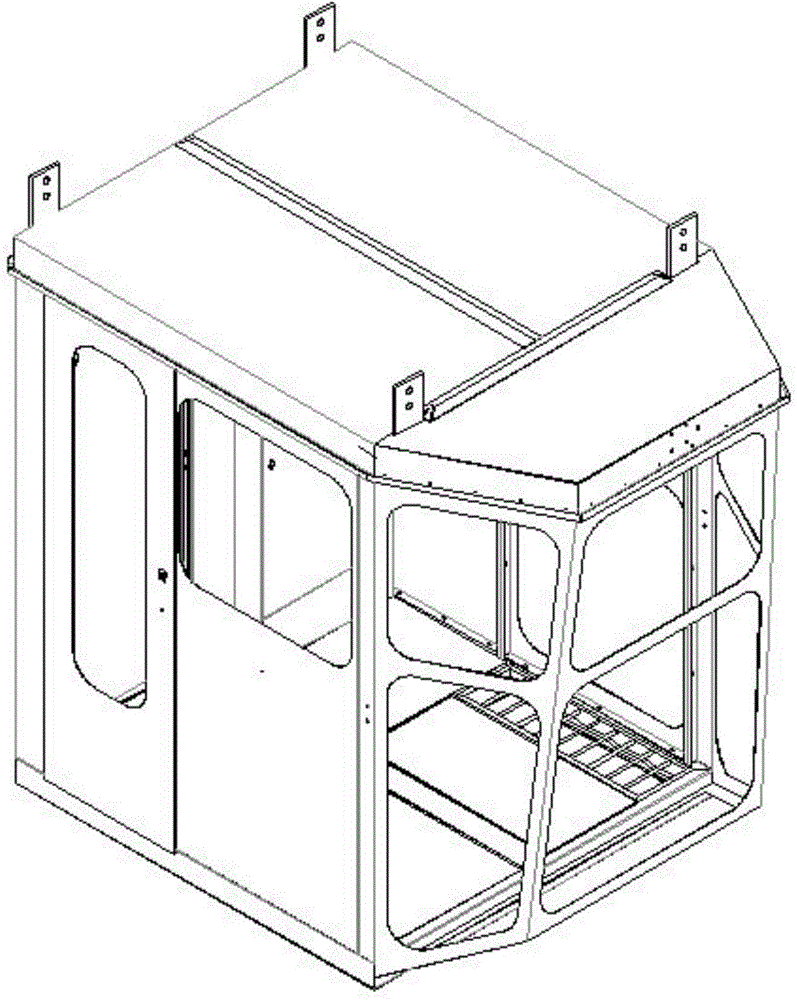
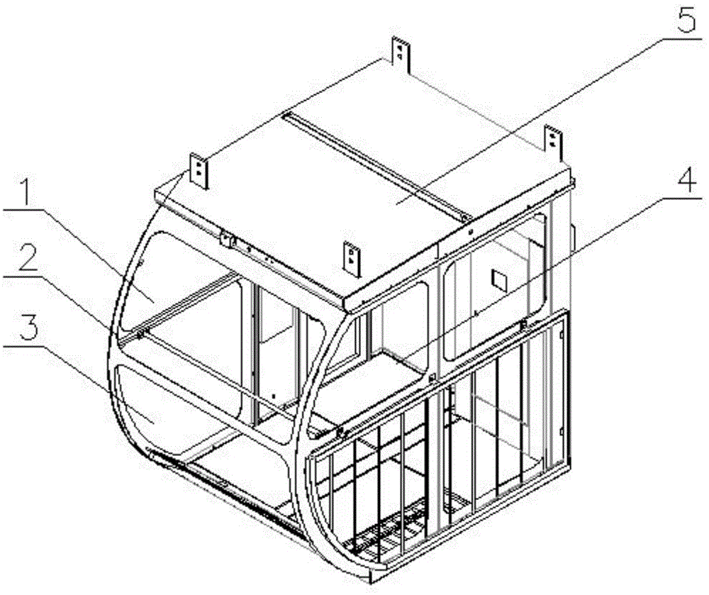
[0011] Lifting equipment control room, including the control room frame; the top, bottom, and back of the control room frame are all equipped with metal plates; the curved surface where the front frame of the control room frame is located is an arc-shaped surface, and the center of the arc-shaped surface is Inside the control room, the front frame of the control room frame is provided with arc-shaped curved glass; the side of the control room frame is provided with sliding glass windows.

[0012] Among them, the front frame of the control room frame is provided with two arc-shaped curved glass.

[0013] The biggest innovation of the present invention is that, according to the convex lens principle, the front of the control room adopts arc-shaped curved glass, which greatly increases the field of vision of the operator.

[0014] The present invention designs a brand-new lif...


PUM


Abstract

The invention discloses a control room for hoisting equipment. The control room comprises a control room skeleton, wherein metal plates are arranged at the top part, the bottom part and the back part of the control room skeleton; the curved surface in which a front skeleton of the control room skeleton is arranged is an arc-shaped curved surface; the center of the arc-shaped curved surface is positioned in the control room; the front skeleton of the control room skeleton is provided with arc-shaped curved glass; and the side surface of the control room skeleton is provided with a sliding glass window. The control room disclosed by the invention has the advantage that the range of the visual field is greatly enlarged so that an operator easily observes the goods and the activity condition of people, thus ensuring good safety.

Description

technical field [0001] The invention relates to the technical field of lifting equipment, in particular to a lifting equipment control room. Background technique [0002] The control room of the lifting equipment is generally installed in mid-air, so that the operator can easily monitor the situation below and the goods above during the lifting process. The upper top surface and the lower floor of the conventional control room are closed with metal plates, and the operator cannot easily observe the situation above and below the lifted cargo, and unsafe factors are prone to occur during the lifting process. Contents of the invention [0003] The technical problem to be solved by the present invention: the upper top surface and the lower floor of the control room of the existing lifting equipment are closed with metal plates, and the operator cannot conveniently observe the situation above and below the lifted cargo, and can only see the front. Unsafe factors are prone to o...

Claims


Application Information

Patent Timeline
IPC IPC(8): B66C13/54
Inventor 胡启
Owner NANJING SWITCHGEAR FACTORY
Learn More