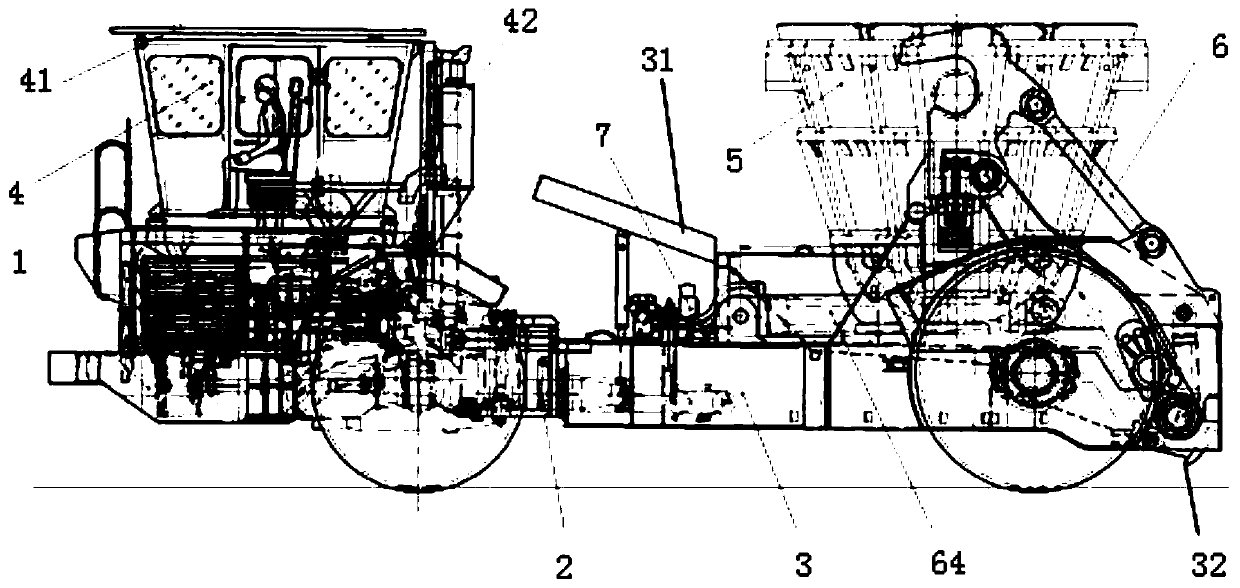
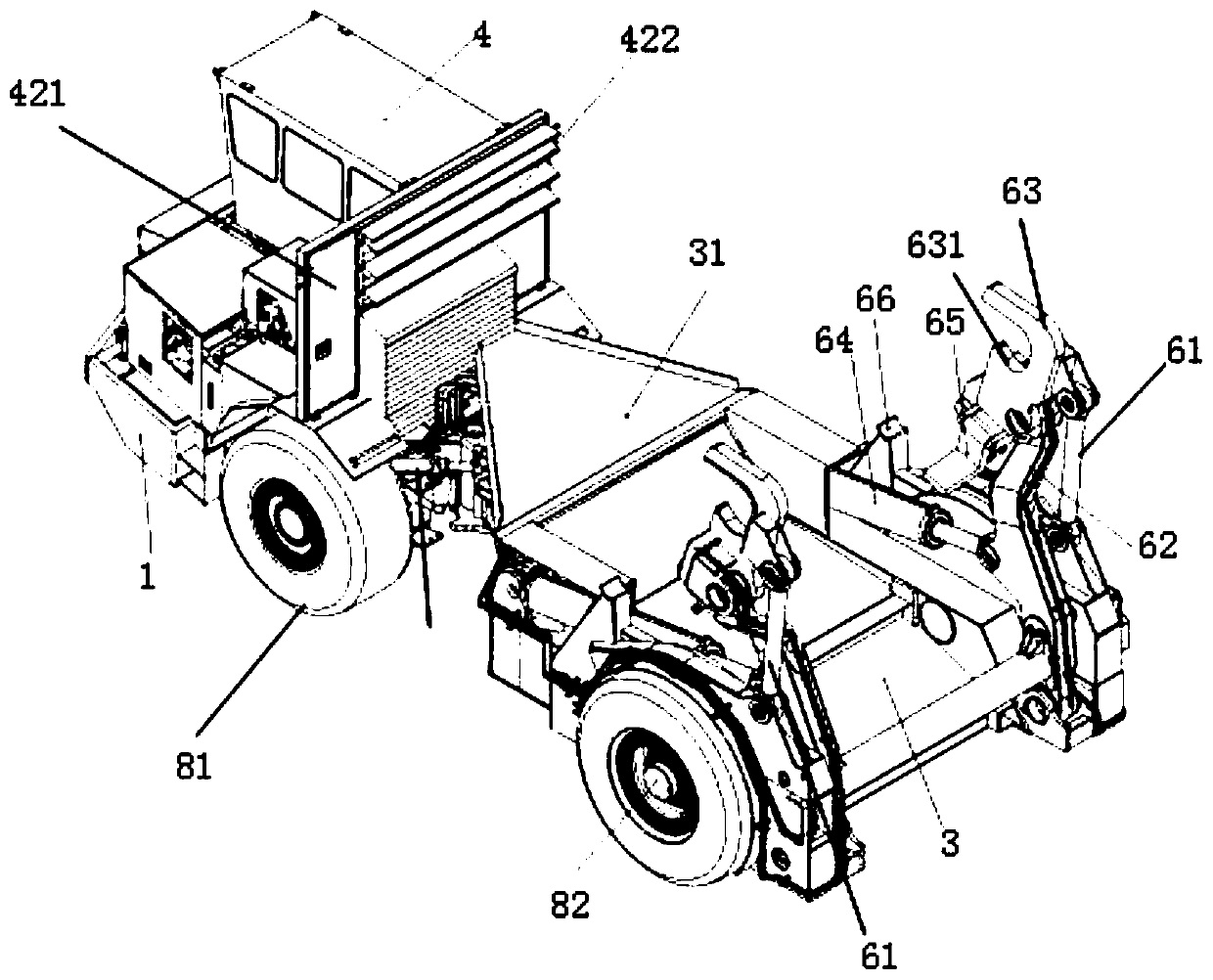
Horizontal articulated slag pot carrier

A technology of holding tank trucks and horizontal hinges is applied in the field of horizontally articulated tank holding trucks, which can solve the problems of high lifting height of slag tank matching, decreased running flexibility of tank trucks, poor stability of carrying operation, etc., and can shorten the lifting and turning of tanks. The effect of working time, improving vision and low labor intensity in production

Active Publication Date: 2019-11-05
MCC BAOSTEEL TECH SERVICE
View PDF9 Cites 2 Cited by
  • Summary
  • Abstract
  • Description
  • Claims
  • Application Information

AI Technical Summary

Problems solved by technology

[0003] Existing articulated tank trucks generally use a gooseneck structure to connect the front and rear frames. This structure is in the form of a casting and has a large volume. Not only is the manufacturing process complicated, but there are inevitably shrinkage cavities, shrinkage porosity, and pores in the manufacturing process. , segregation, sticky sand and cracks and other defects, the structural strength is relatively poor, and the production cost is high
At the same time, with the increasing tonnage of the slag tank, the center of gravity of the slag tank itself is getting higher and higher, the operating flexibility of the tanker is decreasing, the stability of the carrying operation is poor, and the safety is greatly reduced
In addition, there are also disadvantages such as long lifting time during transportation, low operating efficiency, and the need to match a high lifting height for the slag tank, which is a waste of resources.

Method used


Image

  • Horizontal articulated slag pot carrier
  • Horizontal articulated slag pot carrier
  • Horizontal articulated slag pot carrier

Examples


Embodiment Construction

[0069] The specific embodiments of the present invention will be described in further detail below in conjunction with the accompanying drawings. These embodiments are only used to illustrate the present invention, but not to limit the present invention.

[0070] In the description of the present invention, it should be noted that the terms "upper", "lower", "front", "rear", "left", "right", "top", "bottom", "inner", " The orientation or positional relationship indicated by "outer", "horizontal", "vertical", etc. are based on the orientation or positional relationship shown in the drawings, and are only for the convenience of describing the present invention and simplifying the description, rather than indicating or implying the pointed device Or the element must have a specific orientation, be constructed and operated in a specific orientation, and therefore cannot be understood as a limitation of the present invention.

[0071] In the description of the present invention, it sho...


PUM


Abstract

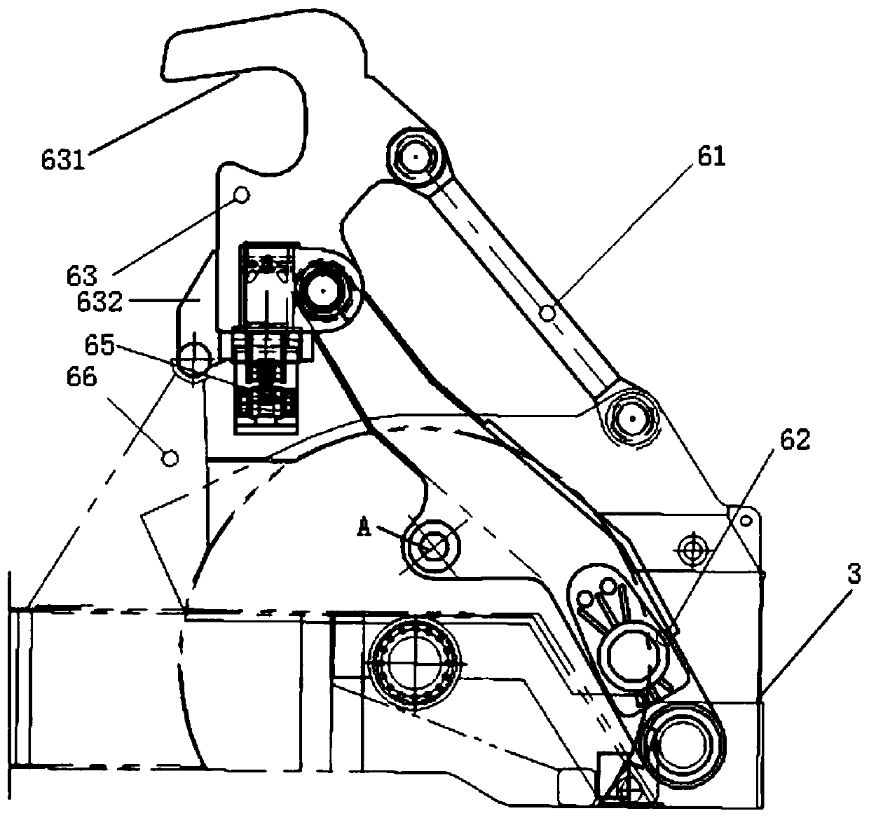
The invention provides a horizontal articulated slag pot carrier. The horizontal articulated slag pot carrier comprises two working mechanisms symmetrically arranged on a rear frame; and the working mechanisms are installed on one sides of the rear frame, and each working mechanism comprises a clamp, a connecting rod, a working big arm and a telescopic rod (64), wherein a U-shaped opening is formed in the clamp, the opening faces towards the direction of a cab and is matched with a trunnion of a slag pot, a pin locking mechanism is arranged on the clamp and is used for locking the slag pot, the bottom of the connecting rod is hinged to the rear frame, the top of the connecting rod is hinged to the outer side of the clamp, the bottom of the working big arm is hinged to the rear frame, the top of the working big arm is hinged to the outer side of the clamp, the working big arm is arranged on the inner side of the connecting rod, the fixed end of the telescopic rod is hinged to the rear frame, and the movable end of the telescopic rod is hinged to the middle part of the working big arm. According to the horizontal articulated slag pot carrier, the problems of long working time, low operation efficiency and the like of an existing slag pot carrier are solved, the safety driving feeling is improved, the whole-vehicle structure is compact, the gravity center is low, and the purposesof high safety, high efficiency, low energy consumption and low cost are achieved.

Description

Technical field [0001] The invention relates to the technical field of metallurgical equipment, in particular to a horizontal articulated tank wagon. Background technique [0002] The metallurgical industry is a pillar industry of a country, and the transportation of metallurgical slag produced in the metallurgical process is directly related to the smooth progress of the entire smelting production process. The slag tanker is mainly used for the transportation and circulation of metallurgical slag and bulk materials. It is an efficient, fast and practical transportation equipment. The current tank trucks are generally divided into articulated, integral and towed types. Among them, the articulated tank truck has the advantages of reasonable overall size and high flexibility. It plays an important role in each production link of the metallurgical industry and has been widely used. Promotion and application. [0003] The existing articulated tank trucks generally use a gooseneck str...

Claims


Application Information

Patent Timeline
Patent Type & Authority Applications(China)
IPC IPC(8): C21B3/10
CPCC21B3/10
Inventor 杨骏李利民谢明闫飞耿会良邱冬平
Owner MCC BAOSTEEL TECH SERVICE
Why Eureka
Try Eureka