Drill jumbo cab

A rock drilling rig and cab technology, applied in the field of construction machinery, can solve the problems of low cab height, operation errors, and inability to clearly see the movement of the boom, so as to increase the height of the field of view and prevent operation errors.

Pending Publication Date: 2018-01-09
HUNAN WUXIN TUNNEL INTELLIGENT EQUIP CO LTD
View PDF8 Cites 0 Cited by
  • Summary
  • Abstract
  • Description
  • Claims
  • Application Information

AI Technical Summary

Problems solved by technology

For existing rock drilling rigs, since the boom often needs to be extended to guide the drill pipe to drill holes when the boom is working, the vertical height of the boom is often relatively large, while the cab of a conventional rock drilling rig is generally directly installed. On the chassis of the car body, the height of the cab of the rock drilling rig is relatively low. Therefore, when the operator sits in the cab of the rock drilling rig and performs operations, he often cannot clearly see the movement of the boom, which may easily lead to operational errors.

Method used


Image

  • Drill jumbo cab
  • Drill jumbo cab
  • Drill jumbo cab

Examples


Embodiment 1

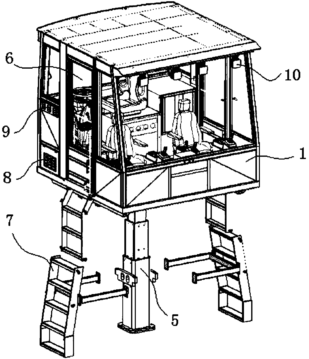
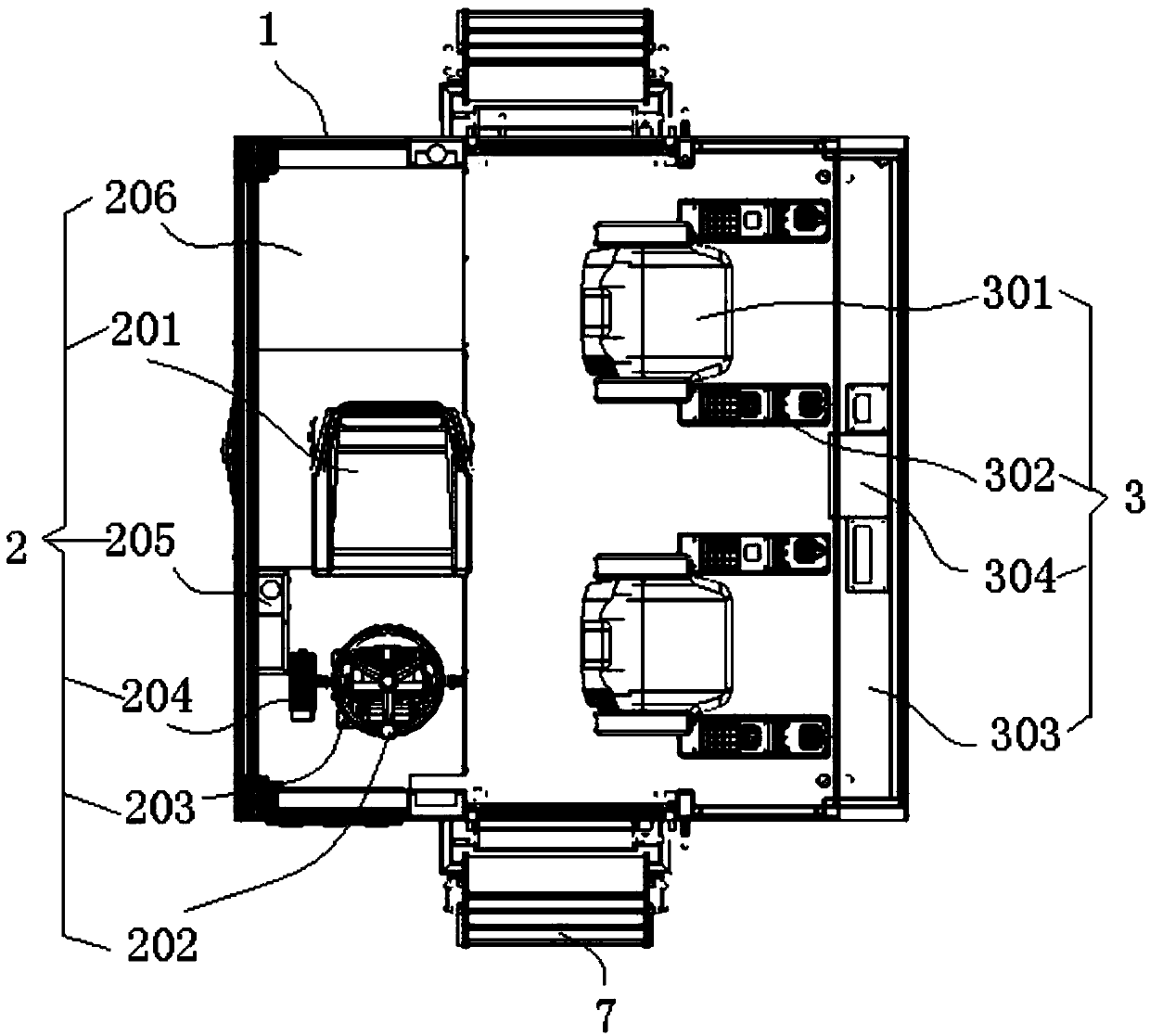
[0025] see figure 1 and figure 2 , figure 1 and figure 2 A specific embodiment of the cab of a rock drilling rig is provided, wherein, figure 1 It is a schematic diagram of the overall structure of a cab of a rock drilling rig disclosed in Embodiment 1 of the present invention; figure 2 It is a top view inside the bin body disclosed in Embodiment 1 of the present invention.

[0026] Such as figure 1 and figure 2 As shown, the present embodiment discloses a cab of a rock drilling jumbo, including a cabin body 1 , a driving control area 2 , a jib control area 3 , a support frame 4 and a jacking device 5 .

[0027] The bin body 1 is the main part of the cab of the rock drilling jumbo, and the actual size of the bin body 1 and the overall layout position on the outer car body are designed according to actual needs.

[0028] The cabin body 1 is provided with a driving control area 2 for vehicle driving control and a jib control area 3 for jib movement control. The drivi...

Embodiment 2

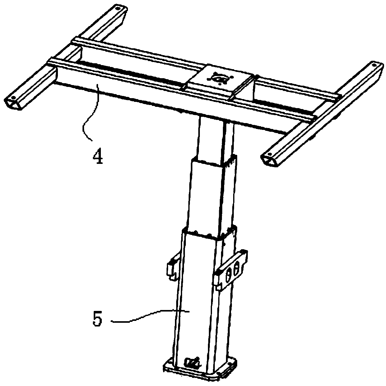
[0042] see Figure 3 to Figure 5 , Figure 3 to Figure 5 A specific embodiment of a jacking device is provided, wherein, image 3 It is a schematic diagram of the external structure of the jacking device disclosed in Embodiment 2 of the present invention; Figure 4 It is a schematic diagram of the internal structure of the jacking device disclosed in Embodiment 2 of the present invention; Figure 5 It is a schematic structural diagram of the spherical mechanism of the jacking device disclosed in Embodiment 2 of the present invention.

[0043] Such as Figure 3 to Figure 5 As shown, this embodiment provides a specific embodiment of a jacking device. The jacking device 5 includes a guide sleeve 501, a telescopic arm 502 slidingly arranged inside the guide sleeve 501, and a telescopic arm 502 arranged on the guide sleeve 501. The jacking cylinder 503 between the telescopic arm 502 , the lower end of the guide sleeve 501 is connected with the vehicle body, and the upper end of...


PUM


Abstract

The invention discloses a drill jumbo cab which comprises a cab body. A driving control area for driving control and a boom control area for boom action control are arranged in the cab body, the driving control area faces a drill jumbo advancing direction, the boom control area faces a boom direction, a jacking device is arranged below a supporting frame which is arranged below the cab body, and the lower portion of the jacking device is mounted on an external drill jumbo body. The drill jumbo cab has advantages that the driving control area for driving control and the boom control area for boom action control are arranged in the cab body, the jacking device is arranged below the cab body, an independent boom action operating area for an operator can be guaranteed through arrangement of the boom control area, vision altitude can be increased by the jacking device which controls the cab body to ascend, and accordingly the operator can conveniently and clearly observe boom actions, and operation errors are effectively prevented.

Description

technical field [0001] The present invention relates to the field of construction machinery, and more specifically relates to a cab of a rock drilling jumbo. Background technique [0002] Rock drilling jumbo is also called drilling jumbo. Rock drilling jumbo is a kind of rock drilling equipment often used in tunnel and underground engineering construction. Rock drilling jumbo generally includes drill pipe, boom (supporting and positioning of rock drilling machine) and propulsion mechanism), car body, running mechanism and other necessary auxiliary equipment. When the rock drilling jumbo is working, the drill pipe moves under the control of the impact mechanism, the drill transfer mechanism, etc., and at the same time drives the drill bit to rotate and impact continuously, so that the drill bit continuously impacts the rock according to the design requirements, and at the same time uses the powder discharge mechanism to discharge stone chips , so that it can be drilled into ...

Claims


Application Information

Patent Timeline
Patent Type & Authority Applications(China)
IPC IPC(8): B62D33/06B62D33/063E21B7/02
Inventor 王祥军龚俊何良军宋祖源高云
Owner HUNAN WUXIN TUNNEL INTELLIGENT EQUIP CO LTD
Why Eureka
Try Eureka