Pull rope type automatic cylinder locking mechanism with self-locking function

An automatic lock and function technology, which is applied to the fixation of guns, weapon accessories, offensive equipment, etc., can solve the problems of false unlocking of the lock, time-consuming and laborious use, and no device that restricts the retraction of the lock.

Active Publication Date: 2014-11-19
BEIJING INST OF SPACE LAUNCH TECH +1
View PDF6 Cites 11 Cited by
  • Summary
  • Abstract
  • Description
  • Claims
  • Application Information

AI Technical Summary

Problems solved by technology

[0003] There are many problems in the current lock cylinder mechanism, such as manual operation is required when unlocking, which is time-consuming and laborious to use, and it is difficult to meet the requirements of modern weaponry for autom

Method used


Image

  • Pull rope type automatic cylinder locking mechanism with self-locking function
  • Pull rope type automatic cylinder locking mechanism with self-locking function
  • Pull rope type automatic cylinder locking mechanism with self-locking function

Examples


Embodiment Construction

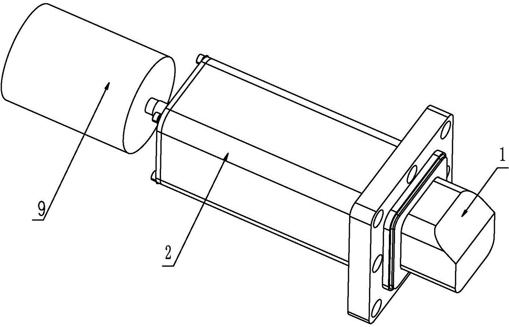
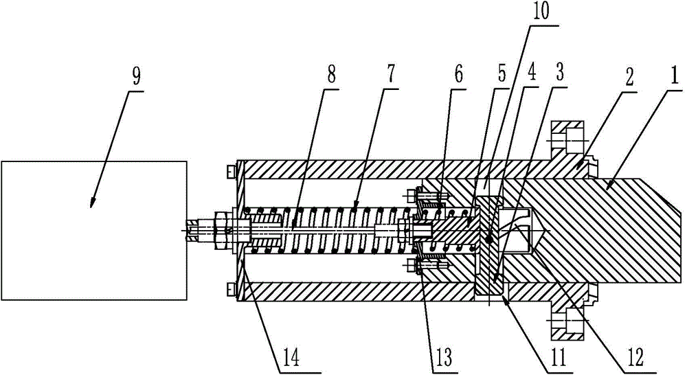
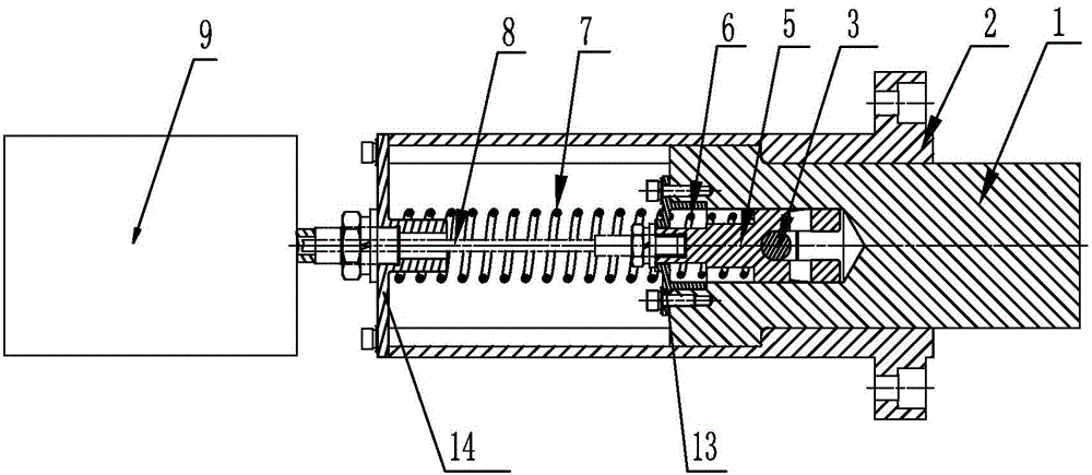
[0017] combine figure 1 , figure 2 and image 3 As shown, the pull cord type automatic locking cylinder mechanism with self-locking function of the present invention includes a lock head 1, a lock sleeve 2, a limit block 3, a guide pin 4, a pull rod 5, a pull rod spring 6, a lock head spring 7, and a pull cord 8 , the cylinder 9, the lock sleeve 2 is a hollow rectangle, the outer wall of the lock sleeve 2 is provided with a limit hole 11, the left end of the lock sleeve 2 is fixedly connected with a lock sleeve end cover 14 by bolts, the right end of the lock sleeve 2 is open, and the lock head 1 is arranged on the lock sleeve 2, the outer surface of the lock head 1 fits the inner surface of the lock sleeve 2, the left end of the lock head 1 is provided with a countersink hole along its longitudinal center, the left end of the countersink hole is fixedly connected with a gland 13 by bolts, and the lock head 1 The middle part near the left end is provided with a guide hole 1...


PUM


Abstract

The invention provides a pull rope type automatic cylinder locking mechanism with a self-locking function, and relates to an automatic cylinder locking mechanism used for locking a launching cylinder. The pull rope type automatic cylinder locking mechanism can automatically achieve the locking action and the unlocking action and can prevent unlocking happening by mistake in the locking process. The pull rope type automatic cylinder locking mechanism comprises a hollow lock sleeve. A limiting hole is formed in the outer wall of the lock sleeve. A tapered end is arranged in the lock sleeve. The outer surface of the tapered head is attached to the inner surface of the lock sleeve. A counterbore is formed in the longitudinal center of the left end of the tapered end. A pull rod with the stair-shaped outer surface is arranged in the counterbore. The middle of the pull rod is sleeved with a pull rod spring. The left end of the pull rod extends out of the left end face of a gland fixedly connected with the left end of the tapered end, and is connected with one end of a pull rope. A tapered end spring is arranged on the left side of the tapered end. The other end of the pull rope sequentially penetrates through the tapered end spring and a lock sleeve end cover fixedly connected with the lock sleeve, and is connected with a cylinder. A transverse guide hole is formed in the tapered end and is a through hole. A limiting block is arranged in the guide hole. A guide pin is fixed to the middle of the limiting block in the front and back direction. An inclined face groove is formed in the right end of the pull rod and is a through hole inclining towards the lower left portion from the right end face of the pull rod. The guide pin can slide in the inclined face groove.

Description

technical field [0001] The invention relates to a cylinder locking mechanism, in particular to an automatic cylinder locking mechanism for locking a launching cylinder. Background technique [0002] In the field of weapon cold launch technology, the launch tube needs to be locked during transportation, storage and erection, so as to ensure that the launch tube and its internal products are positioned correctly and securely. Therefore, a lock cylinder mechanism is required to achieve this function. [0003] There are many problems in the current lock cylinder mechanism, such as manual operation is required when unlocking, which is time-consuming and laborious to use, and it is difficult to meet the requirements of modern weaponry for automation and quick response; there is no device that restricts the retraction of the lock head when locking. When encountering vibration and friction, the lock head may be unlocked by mistake, causing the launch tube and internal products to f...

Claims


Application Information

Patent Timeline
IPC IPC(8): F41A23/50F41A23/00
Inventor 刘奇刘国英杭立杰张博宇贾延奎吴新跃陈劲松曾玲芳
Owner BEIJING INST OF SPACE LAUNCH TECH
Why Eureka
Try Eureka