
Insulated wire pay-off stand

A technology of insulated wires and pay-off racks, applied in the direction of cable laying equipment, etc., can solve the problem of inconvenient portability of pay-off racks, and achieve the effect of time-consuming and labor-intensive changes and easy portability

Inactive Publication Date: 2014-11-26
STATE GRID CORP OF CHINA +1
View PDF5 Cites 0 Cited by
  • Summary
  • Abstract
  • Description
  • Claims
  • Application Information

AI Technical Summary

Problems solved by technology

[0003] The purpose of the present invention is to provide an insulated wire pay-off stand, which can effectively solve the problem that the existing pay-off stand is not easy to carry

Method used


Image

  • Insulated wire pay-off stand
  • Insulated wire pay-off stand
  • Insulated wire pay-off stand

Examples


Embodiment Construction

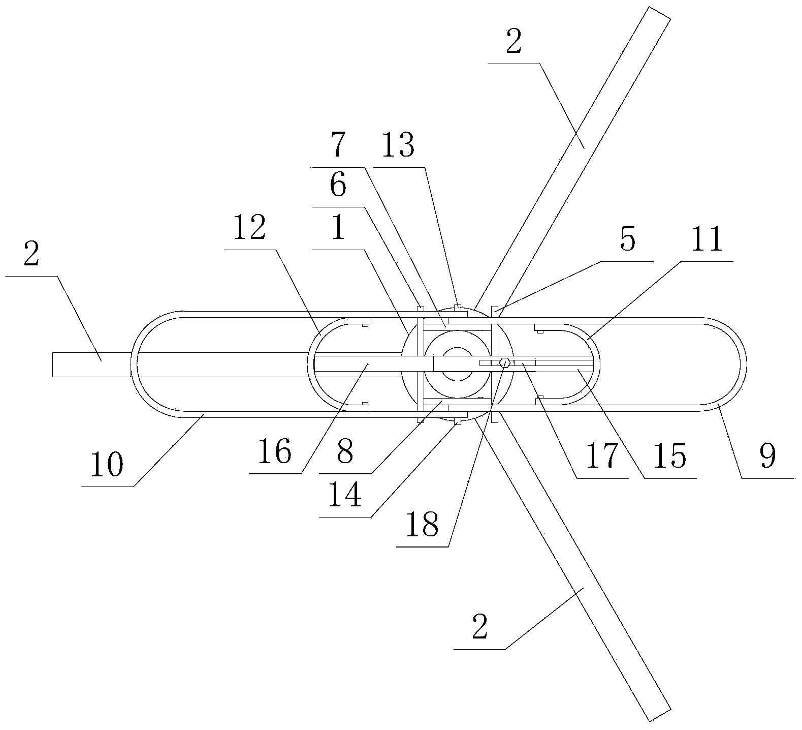
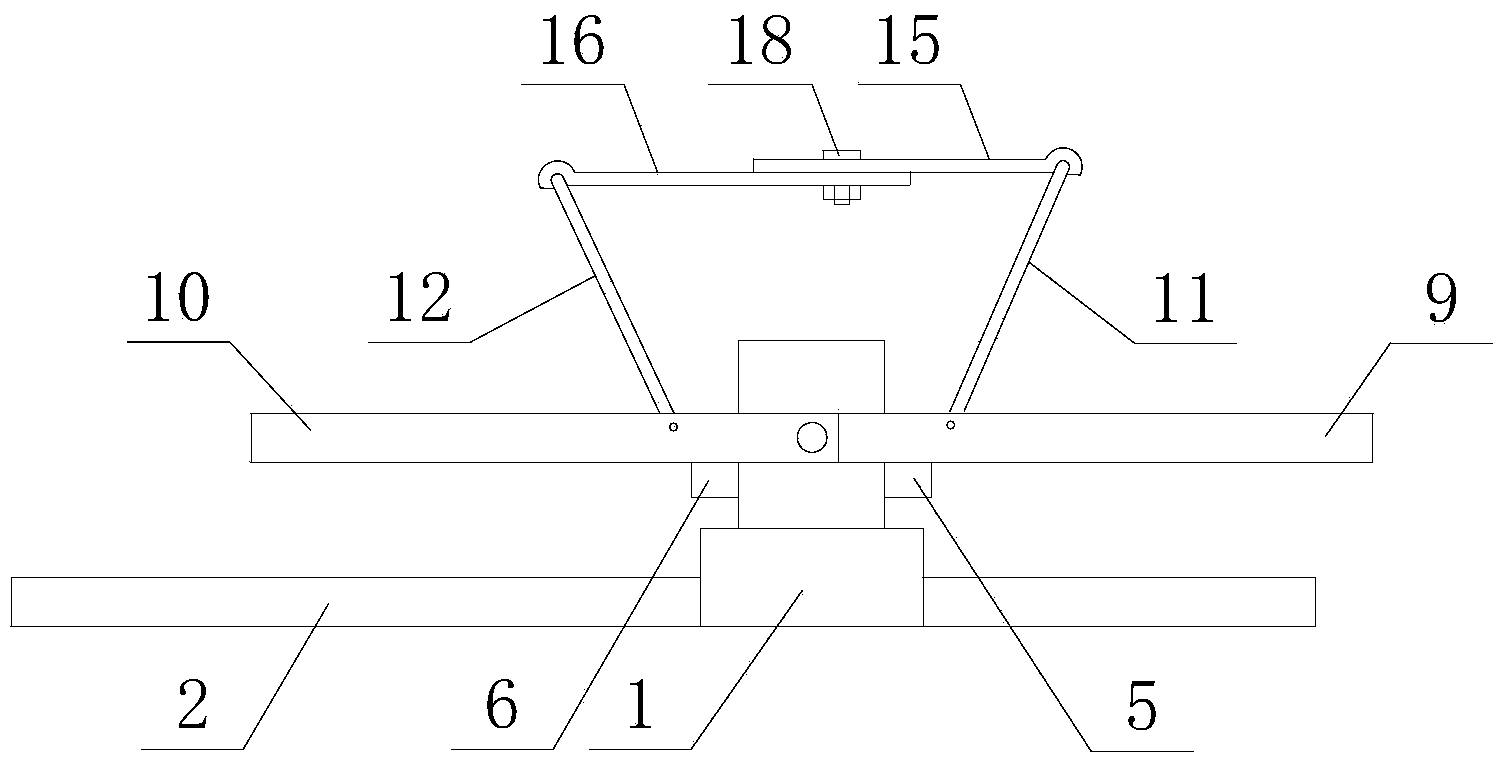
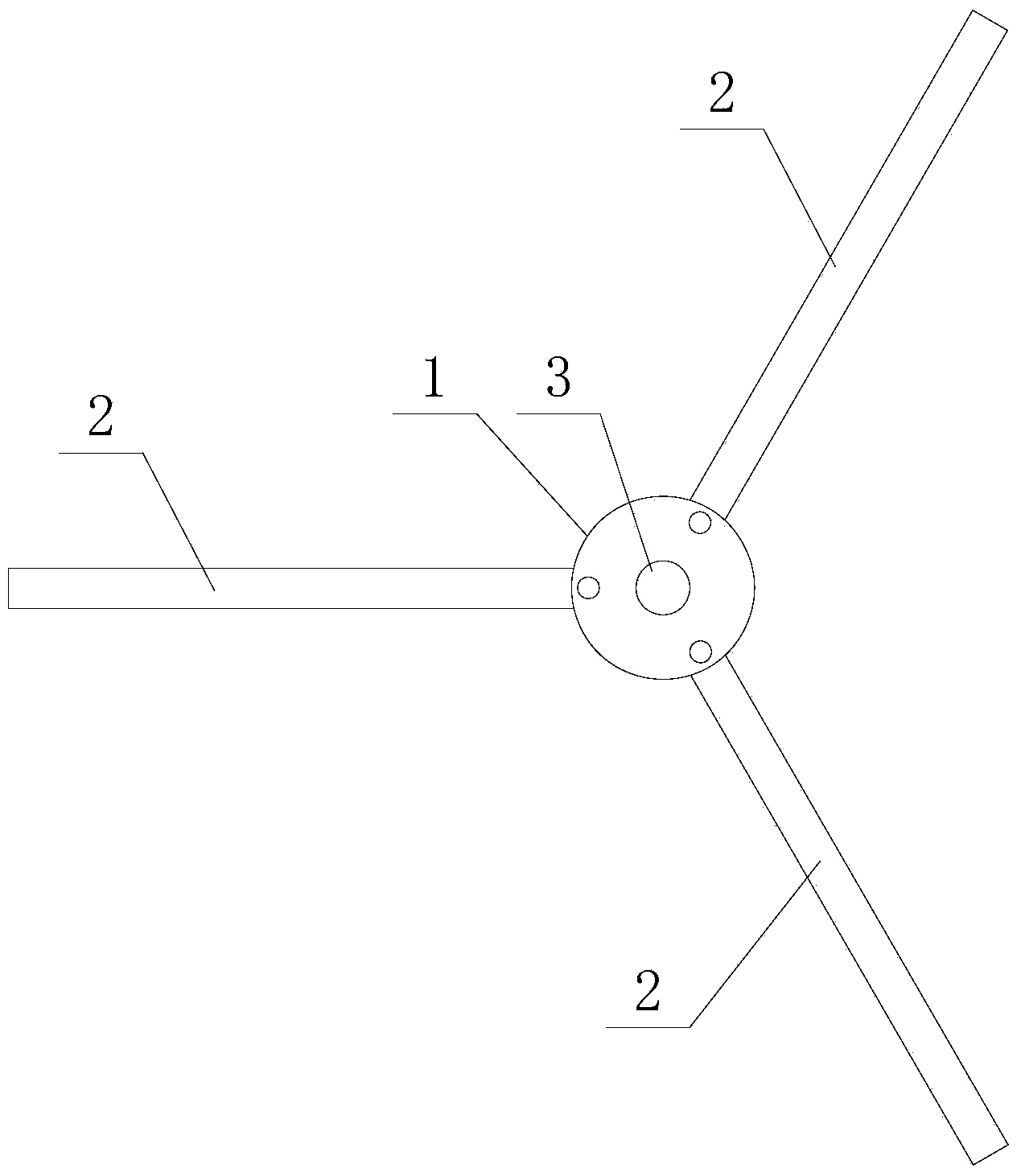
[0016] refer to figure 1 , figure 2 As shown, it is an embodiment of an insulated wire pay-off frame of the present invention, an insulated wire pay-off frame, including a folding base and a lead frame rotatably connected to the folding base;

[0017] The folding base includes a disc base 1, three legs 2 that are rotatably connected to the disc base 1, a main rotating shaft 3 fixed on the center of the disc base 1, and three turning points between the three legs 2 and the disc base 1. The distance to the center of the disc base 1 is equal;

[0018] The lead frame includes a sleeve 4 sleeved on the main shaft 3, a front main rod 5 fixedly connected to the front side wall of the sleeve 4, a rear main rod 5 fixedly connected to the rear side wall of the sleeve 4 and parallel to the front main rod 5. Rod 6, the left main rod 7 that is fixedly connected with front main rod 5 and rear main rod 6 on the left side of sleeve post 4 and is perpendicular to front main rod 5, is arrang...


PUM


Abstract

The invention discloses an insulated wire pay-off stand which comprises a folding base and a wire frame connected to the folding base in a rotating mode. The folding base comprises a disc base, three supporting legs connected to the disc base in a rotating mode, and a main rotating shaft fixed to the center of the disc base. The wire frame comprises a sleeve pillar arranged on the main rotating shaft in a sleeved mode, four main rods fixed to the periphery of the sleeve pillar, a front bottom support connected with the main rods and arranged in front of the sleeve pillar, a front wire support connected to the front bottom support in a rotating mode, a rear bottom support connected with the main rods in a rotating mode and arranged behind the sleeve pillar, a rear wire support connected to the rear bottom support in a rotating mode, and a distance adjusting device arranged between the front wire support and the rear wire support. The insulated wire pay-off stand has the advantages that one to two persons are enough to operate the insulated wire pay-off stand, multiple coils of wires can be paid off at a time smoothly, the insulated wire pay-off stand is convenient to carry, the clamping phenomena such as wire knotting can be avoided, and the average pay-off time is shortened to five minutes from the original thirty minutes.

Description

technical field [0001] The invention relates to an insulated wire pay-off frame. Background technique [0002] In the process of household connection transformation in line construction, it is often necessary to lay insulated wires. The manual laying-out method is labor-intensive, low-efficiency, time-consuming and labor-intensive, and it is easy to damage the insulation layer of the wires. The volume is relatively large, although it can reduce the labor intensity, it is not easy to carry, and it is very inconvenient to carry the pay-off rack. Contents of the invention [0003] The object of the present invention is to provide an insulated wire pay-off stand, which can effectively solve the problem that the existing pay-off stand is not easy to carry. [0004] In order to solve the above-mentioned technical problems, the present invention is achieved through the following technical solutions: an insulated wire pay-off frame, comprising a folding base and a lead frame rota...

Claims


Application Information

Patent Timeline
Patent Type & Authority Applications(China)
IPC IPC(8): H02G1/06
Inventor 贺伟军林巨军虞伟姜才军戴浩斌
Owner STATE GRID CORP OF CHINA
Learn More