
Insulated wire pay-off rack grounding device applicable to power distribution cabinet

A technology of insulated wires and grounding devices, which is applied in the field of pay-off racks, can solve problems such as safety production impacts, safety hazards, and increase the difficulty of releasing wires, and achieve the effect of time-consuming and labor-intensive changes and easy portability

Inactive Publication Date: 2017-10-03
苏州基弘电气设备制造有限公司
View PDF2 Cites 0 Cited by
  • Summary
  • Abstract
  • Description
  • Claims
  • Application Information

AI Technical Summary

Problems solved by technology

[0002] In recent years, the power safety situation is relatively severe, and various accidents have occurred, among which casualties caused by the release of wires have also occurred from time to time. At present, the power supply bureau uses the release end to play the role of grounding through pulleys and iron brazing during the process of releasing bare wires. , this method is simple and effective, but it is not suitable for insulated wires
There is no grounding device in the process of laying insulated wires, which creates a certain potential safety hazard
At present, the line corridor is complicated, and there are many high and low voltage crossings. The 10kV line crosses with the high voltage level line to generate an induced current, and there are some high and low voltage power supply phenomena at the intersection with the low voltage line. This series of phenomena will have a certain impact on safe production. , especially increasing the difficulty of casting wires

Method used


Image

  • Insulated wire pay-off rack grounding device applicable to power distribution cabinet

Examples


Embodiment Construction

[0011] The present invention will be further described below in combination with the accompanying drawings and specific embodiments.

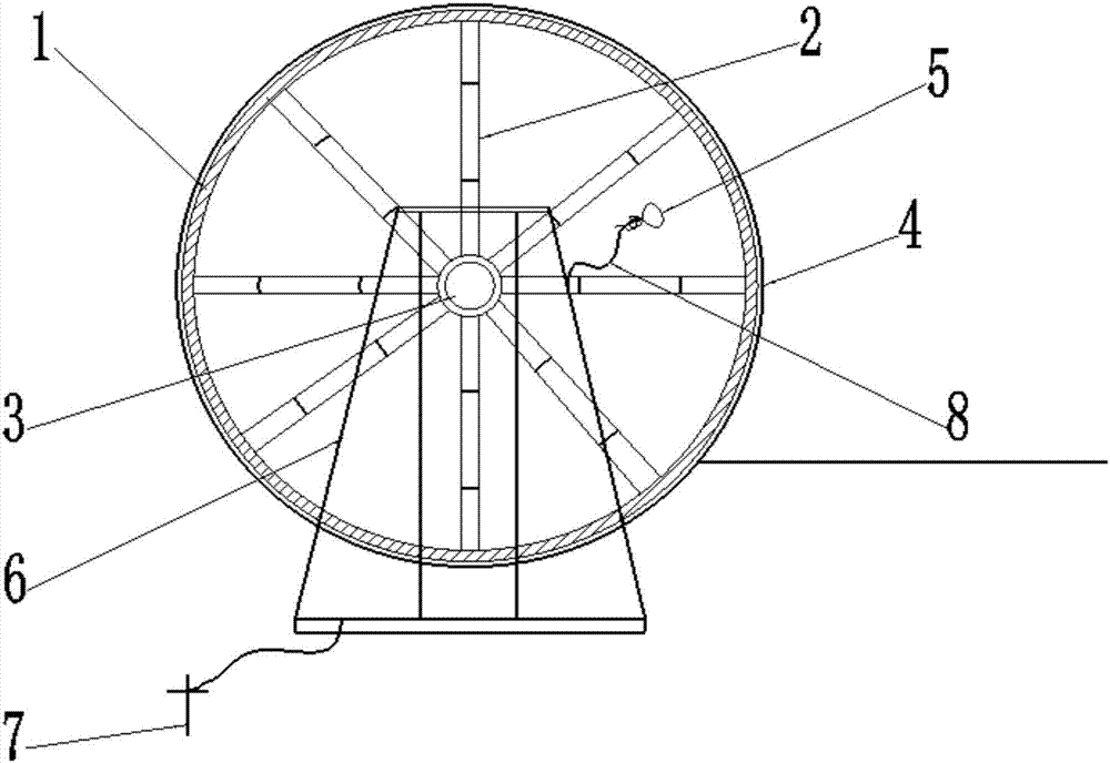
[0012] Such as figure 1 As shown, a grounding device for an insulated wire pay-off frame suitable for a power distribution cabinet is mainly composed of a wire reel 1, a wire reel iron frame 2, a wire reel center shaft 3, an insulated wire 4, a puncture wire clamp 5, and a wire release frame 6 And, ground pole 7 and annealed copper wire 8, described wire reel 1 is provided with wire reel iron frame 2, and wire reel iron frame 2 center position is provided with wire reel axis 3, and wire reel 1 is provided with insulated wire 4, The end of the insulated conductor 4 is connected to the annealed copper wire 8, and the annealed copper wire 8 is connected to the iron frame 2 of the reel by using the puncture clamp 5, and the central axis 3 of the reel is connected to the pay-off rack 6; the pay-off rack 6 is connected to the ground electrode 7 are ...


PUM


Abstract

The invention discloses an insulated wire pay-off rack grounding device applicable to a power distribution cabinet. The device is mainly composed of a wire coil, a wire coil iron frame, a wire coil middle shaft, an insulated wire, a penetrated clip, a pay-off rack, a grounding electrode and a soft copper wire. The wire coil iron frame is arranged in the wire coil, the wire coil middle shaft is arranged in the center of the wire coil iron frame, the wire coil is provided with the insulated wire, the tail of the insulated wire is connected with the soft copper wire, the soft copper wire is connected to the wire coil iron frame through the penetrated clip, and the wire coil middle shaft is connected with the pay-off rack. The adverse factors that traditional pay-off methods waste time and labor, wire insulation layers are likely to be damaged, toppling is likely to be caused and safety is low are thoroughly changed, the device is handy, convenient to carry, free of wire knotting, clamping or other phenomena, and easily, practically, conveniently and reliably applicable to the power distribution cabinet, solves the problem that the insulated wire cannot be grounded in the release process, and is applied in practice.

Description

technical field [0001] The invention belongs to the technical field of pay-off racks, and in particular relates to a grounding device for an insulated wire pay-off rack suitable for a power distribution cabinet. Background technique [0002] In recent years, the power safety situation is relatively severe, and various accidents have occurred, among which casualties caused by the release of wires have also occurred from time to time. At present, the power supply bureau uses the release end to play the role of grounding through pulleys and iron brazing during the process of releasing bare wires. , this method is simple and effective, but it is not suitable for insulated wires. There is no grounding device during the deployment of insulated wires, which poses a certain safety hazard. At present, the line corridor is complicated, and there are many high and low voltage crossings. The 10kV line crosses with the high voltage level line to generate an induced current, and there ar...

Claims


Application Information

Patent Timeline
Patent Type & Authority Applications(China)
IPC IPC(8): B65H49/30H01R4/64H01R4/66
CPCB65H49/30B65H2701/34H01R4/64H01R4/66
Inventor 沈建李冬华杜林周超陈伟浩许宏新
Owner 苏州基弘电气设备制造有限公司
Learn More