Fast smoke removing device

A smoke and fast technology, which is applied in the fields of combination device, dispersed particle separation, chemical instruments and methods, etc., can solve the problems of difficult cleaning, poor smoke removal effect, slow suction speed, etc., and achieves convenient device cleaning and fast suction speed. , the effect of clean air

Inactive Publication Date: 2014-12-03
FUJIAN ZHONGJIN NEW MATERIALS
View PDF4 Cites 0 Cited by
  • Summary
  • Abstract
  • Description
  • Claims
  • Application Information

AI Technical Summary

Problems solved by technology

The fan suction method has the following problems: 1. The suction speed is slow; 2. The smoke removal effect is poor; 3. Oil mist will be attached to the fan impeller, which is difficult to clean

Method used


Image

  • Fast smoke removing device

Examples


Embodiment Construction

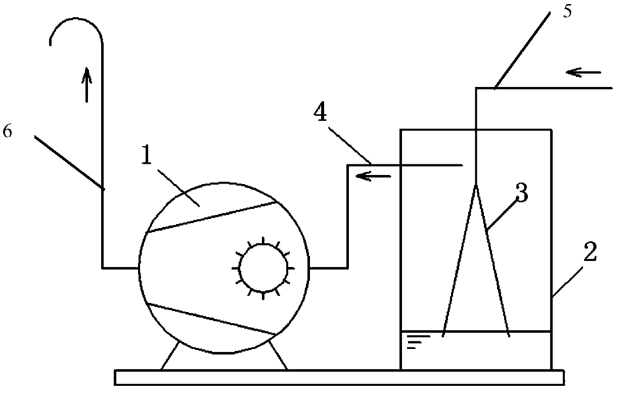
[0026] Please check figure 1 , a quick smoke removal device, including a storage tank 2, an air inlet pipe 5, an exhaust pipe 4, a liquid ring vacuum pump 1 and a chimney pipe 6.

[0027] The storage tank 2 has a circular bottom wall, a rotary peripheral wall extending upward from the periphery of the circular bottom wall, and a sealing cover connected to the upper port of the rotary peripheral wall. The sealing cover is provided with a through hole penetrating up and down. In this embodiment, the revolving peripheral wall is, for example, a cylindrical wall. The rotary peripheral wall is provided with a through opening through which the inside and outside penetrate. The storage tank is filled with liquid, and the liquid level is spaced from the sealing cover. The height of the through opening is higher than the liquid level.

[0028] The air intake pipe 5, the first end is connected to the suction point, such as the suction point connected to the smog workshop, or the suctio...


PUM

PropertyMeasurementUnit
angleaaaaaaaaaa

Abstract

The invention discloses a fast smoke removing device. The fast smoke removing device comprises a storage tank, a gas inlet pipe, a gas exhausting pipe and a vacuum pump, wherein the storage tank is provided with a round bottom wall, a rotary peripheral wall and a sealing cover; the rotary peripheral wall is provided with a penetrating hole; liquid is contained in the storage tank, space is reserved between the liquid level and the sealing cover; the penetrating hole is higher than the liquid level. The first end of the gas inlet pipe is communicated with a sucking point, and the second end of the gas inlet pipe penetrates through the sealing cover in a sealing manner from top to bottom so as to extend into the storage tank, and is communicated with a communicating pipe; the section area of an inner hole of the communicating pipe is increased gradually from top to bottom, and a lower end opening of the communicating pipe is inserted into the liquid; the first end of the gas exhausting pipe is communicated with the penetrating hole, and one section, which corresponds to the first end, of the gas exhausting pipe is arranged along the tangential direction of the penetrating hole of the rotary peripheral wall; an inlet of the vacuum pump is communicated with the second end of the gas exhausting pipe, and an outlet of the vacuum pump is an exhausting hole. The fast smoke removing device has the following advantages that the sucking speed is high; the smoke-removing effect is good; after the smoke is removed from gas, the gas enters the vacuum pump, so that the air is clean and the operation life is long.

Description

technical field [0001] The invention relates to a quick smoke removal device. Background technique [0002] Various kinds of smoke may be generated during the production process, and the existence of smoke will deteriorate the working environment of the production space and reduce the yield of products. In order to improve the working environment and increase the yield of products, the smoke needs to be sucked away in time. The current common way is to use a fan to suck it. The fan suction method has the following problems: 1. The suction speed is slow; 2. The smoke removal effect is poor; 3. The oil mist will be attached to the fan impeller, which is difficult to clean. Contents of the invention [0003] The invention provides a quick smoke removal device, which overcomes the shortcomings of the smoke removal device in the background art. [0004] The adopted technical scheme that the present invention solves its technical problem is: [0005] A quick smoke removal dev...

Claims


Application Information

Patent Timeline
Patent Type & Authority Applications(China)
IPC IPC(8): B01D50/00
Inventor 彭建华吴道斌
Owner FUJIAN ZHONGJIN NEW MATERIALS
Why Eureka
Try Eureka