Automatic discharge circuit and discharge method for energy storage element when power is off

A technology of automatic discharge and energy storage components, which is applied in the field of automatic discharge of energy storage components, automatic discharge circuits, and automatic discharge circuits of energy storage components to achieve the effects of optimizing equipment performance, ensuring discharge safety, and avoiding waste of power consumption

Inactive Publication Date: 2017-09-08
山东华芯电子有限公司
View PDF7 Cites 0 Cited by
  • Summary
  • Abstract
  • Description
  • Claims
  • Application Information

AI Technical Summary

Problems solved by technology

However, the discharge resistor will produce a constant power loss after the AC power is turned on. Taking the discharge resistor 2MΩ as an example, when the AC input voltage is 250V, the continuous power consumption brought by the discharge resistor is 35mV, which is causing no-load and standby input power. important factor in consumption

Method used


Image

  • Automatic discharge circuit and discharge method for energy storage element when power is off
  • Automatic discharge circuit and discharge method for energy storage element when power is off
  • Automatic discharge circuit and discharge method for energy storage element when power is off

Examples


Embodiment 1

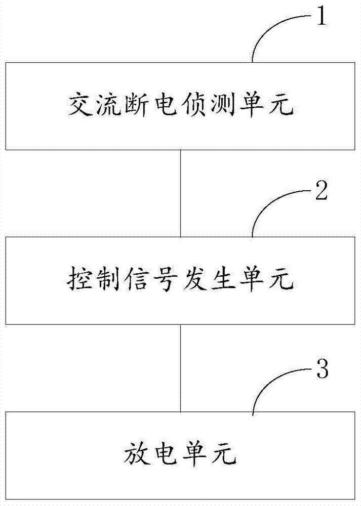
[0054] see figure 1 , the present invention discloses an automatic discharge circuit for an energy storage element when the power is cut off. The automatic discharge circuit includes an AC power failure detection unit 1 , a control signal generation unit 2 and a discharge unit 3 connected in sequence. In this embodiment, the energy storage element is an X capacitor, of course, it may also be other energy storage elements.

[0055] The AC power failure detection unit 1 is coupled to both ends of the X capacitor through two diodes and a resistor to determine whether the AC power is disconnected; the control signal generation unit 2 is connected to the AC power failure detection unit 1 and the discharge unit 3 connected, if the control signal generating unit 2 obtains the signal that the AC power is disconnected from the AC power failure detection unit 1, it controls the discharge unit 3 to discharge the X capacitor.

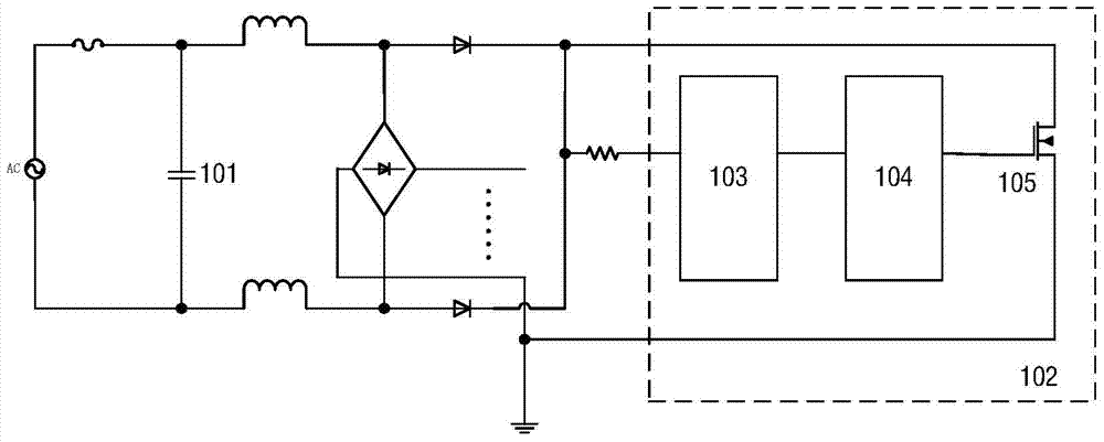
[0056] see figure 2 In the figure, 101 is the energy stora...

Embodiment 2

[0074] The present invention discloses an automatic discharge circuit for an energy storage element when power is cut off. The automatic discharge circuit includes: an AC power failure detection unit, a control signal generation unit, and a discharge unit;

[0075] The AC power failure detection unit is used to judge whether the AC power is disconnected; for example, it can be judged by coupling two diodes and resistors (or other components) to both ends of the energy storage element.

[0076] The control signal generation unit is connected with the AC power failure detection unit and the discharge unit. If the control signal generation unit obtains the signal of AC power disconnection from the AC power failure detection unit, it controls the discharge unit to discharge the energy storage element.

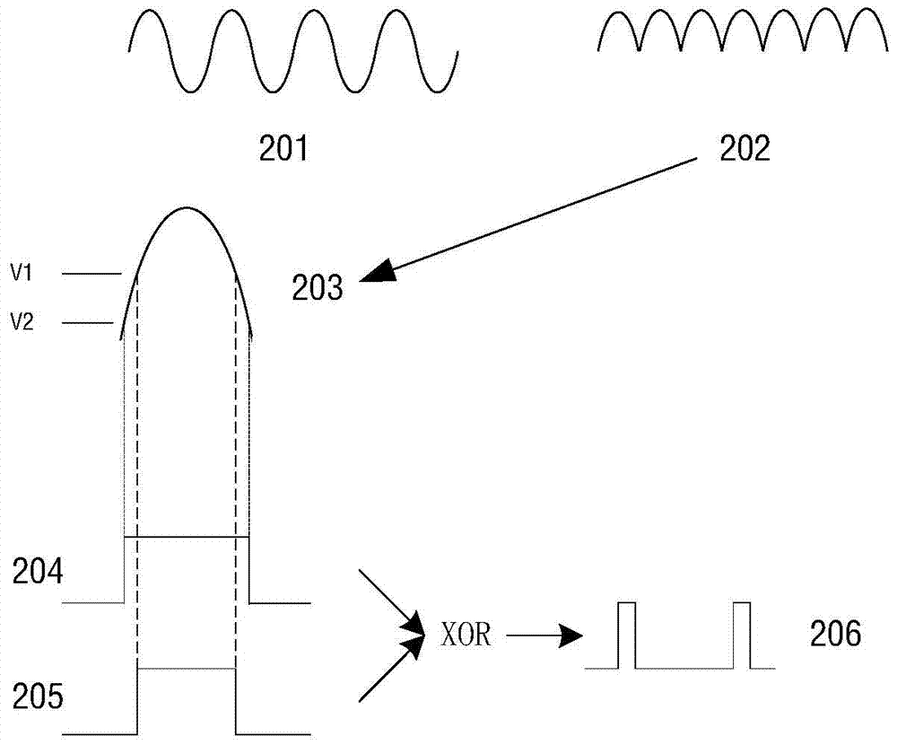
[0077] In this embodiment, the AC detection unit may include: a half-wave rectification module, two square wave conversion modules, and a pulse signal generation module. The half-w...


PUM


Abstract

The invention discloses an automatic discharging circuit for outage of an energy storage element and a discharging method thereof. The automatic discharging circuit comprises alternating current outage detection units, a control signal generation unit and a discharging unit. The alternating current outage detection units are coupled to the two ends of the energy storage element through two diodes and resistors and used for judging whether alternating currents are disconnected. The control signal generation unit is connected with the alternating current outage detection units and the discharging unit and controls the discharging unit to discharge for the energy storage element when obtaining the signal that the alternating currents are disconnected from the alternating current outage detection units. According to the automatic discharging circuit of the energy storage element, the discharging safety of the energy storage element such as a capacitor X can be guaranteed, and power consumption waste caused by a discharging resistor of the energy storage element can be reduced and even avoided.

Description

technical field [0001] The invention belongs to the technical field of electronic circuits, and relates to an automatic discharge circuit, in particular to an automatic discharge circuit for an energy storage element when it is powered off; meanwhile, the invention also relates to an automatic discharge method for an energy storage element when it is powered off. Background technique [0002] During the use of household appliances, X capacitors are usually placed between the input terminals of the power supply to filter EMI noise. Because they can store high-voltage electrical energy for a long time after the AC power is cut off, they are easy to pose a safety threat. [0003] The safety specification stipulates that the X capacitor must be connected with a discharge resistor in parallel to discharge the X capacitor. However, the discharge resistor will produce a constant power loss after the AC power is turned on. Taking the discharge resistor 2MΩ as an example, when the A...

Claims


Application Information

Patent Timeline
Patent Type & Authority Patents(China)
IPC IPC(8): H02M1/44
Inventor 付关军
Owner 山东华芯电子有限公司
Why Eureka
Try Eureka