Rotatably placed energy-saving oven

An energy-saving, oven technology, applied in drying, drying machine, drying gas layout and other directions, can solve the problems of insufficient uniform contact between materials and high-temperature air, unsafe gas discharge of waste heat, and low drying efficiency of materials, etc. The effect of stable placement, ensuring safe discharge and improving contact efficiency

Inactive Publication Date: 2018-06-22
ZHENGZHOU MOORE ELECTRONICS INFORMATION TECH CO LTD
View PDF6 Cites 0 Cited by
  • Summary
  • Abstract
  • Description
  • Claims
  • Application Information

AI Technical Summary

Problems solved by technology

[0003] Existing ovens have low efficiency when airflow heats and dries materials, the contact between materials and high-temperature air is not uniform enough, and the energy utilization rate is low; the placement of materials in the oven is generally placed directly on the grid support, which is not conducive to the interaction with hot air Contact, the accumulation and placement of a large amount of materials will also cause the doping of materials; it is not safe to directly discharge the gas with waste heat when the oven is heated, and some waste heat will also cause energy waste

Method used


Image

  • Rotatably placed energy-saving oven
  • Rotatably placed energy-saving oven
  • Rotatably placed energy-saving oven

Examples


Embodiment Construction

[0021] The following will clearly and completely describe the technical solutions in the embodiments of the present invention with reference to the accompanying drawings in the embodiments of the present invention. Obviously, the described embodiments are only some, not all, embodiments of the present invention. Based on the embodiments of the present invention, all other embodiments obtained by persons of ordinary skill in the art without making creative efforts belong to the protection scope of the present invention.

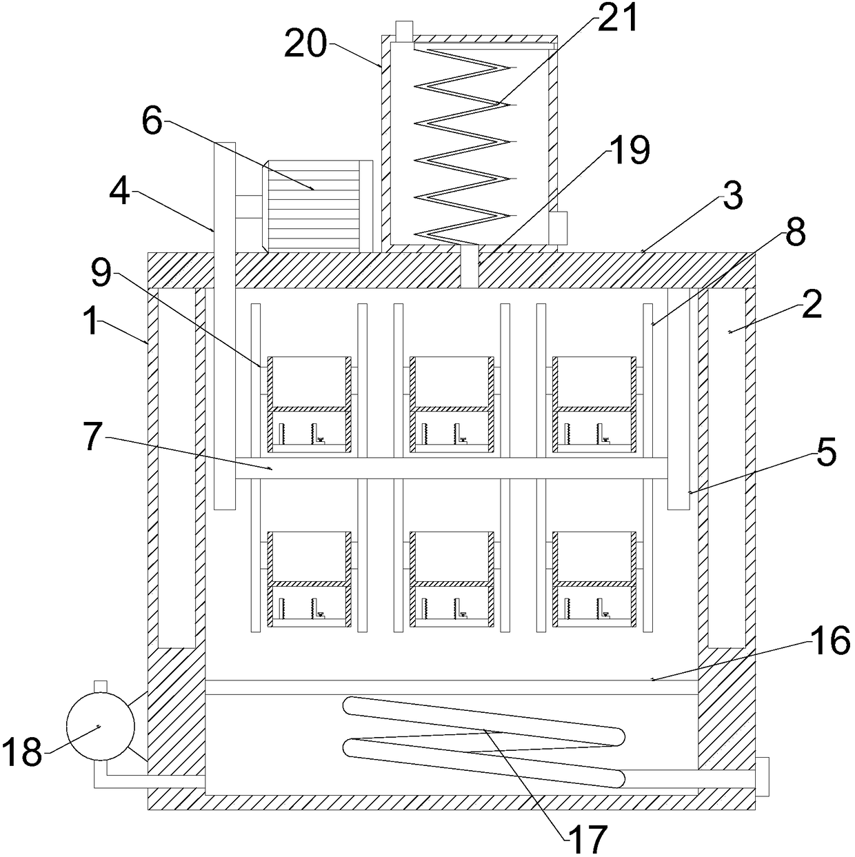
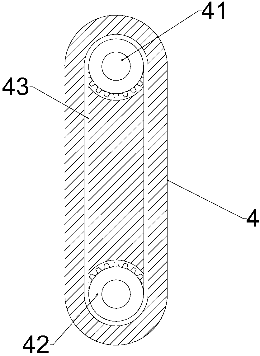
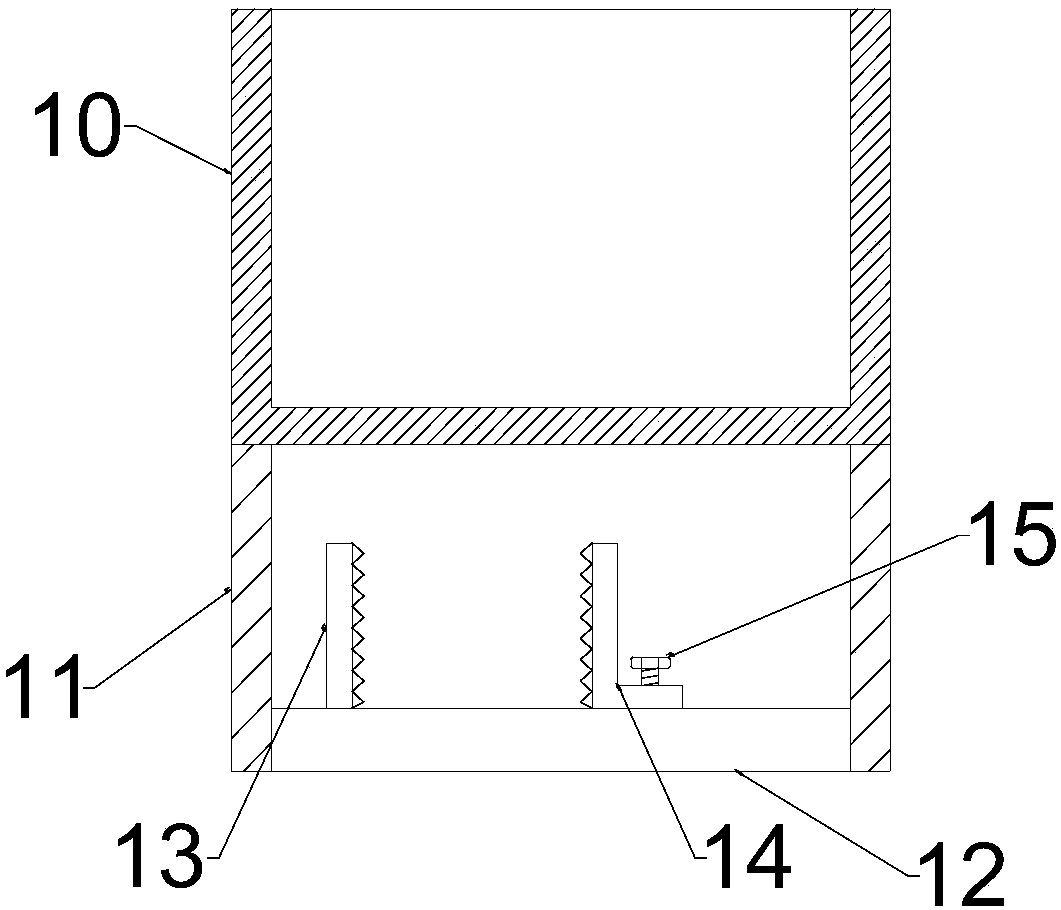
[0022] see Figure 1-3 , in an embodiment of the present invention, a rotationally placed energy-saving oven includes a housing 1, and the two side walls of the housing 1 are symmetrically embedded with electro-hydraulic push rods 2, and the electro-hydraulic push rods 2 are driven by a two-way gear pump , oil cylinder, oil circuit integrated block and piston rod are integrated, the output end of the electro-hydraulic push rod 2 moves through the upper end of ...


PUM


Abstract

The invention discloses a rotatably placed energy-saving oven. The rotatably placed energy-saving oven comprises a shell, wherein electric hydraulic push rods are arranged on two sides of the shell; aplacing cover plate is arranged at the upper ends of the electric hydraulic push rods; a supporting plate shell and a side supporting plate are arranged on the placing cover plate; a driving chain wheel, a driven chain wheel and a transmission chain are arranged on the side wall of the supporting plate shell; the right end of the driving chain wheel is connected to a motor; a placing rotary shaftis arranged between the driven chain wheel and the side supporting plate; placing supporting plates are arranged in the periphery of the placing rotary shaft in a cross manner; a placing box is connected between the placing supporting plates through rotating pins; a connecting rod and a counterweight bottom plate are arranged at the lower end of the placing box; a fixed clip and a movable clip are arranged on the counterweight bottom plate; an electric heating wire is arranged in the bottom of the shell; an air pump is arranged on the left side of the shell; a heat exchange cavity is formed in the upper end of the placing cover plate; and a heat exchange pipeline is arranged in the heat exchange cavity. The rotatably placed energy-saving oven disclosed by the invention can dry materials by heating air, promote uniform heating of the materials by rotating the placing box and the counterweight bottom plate, and recover waste heat by additionally arranging the heat exchange cavity, so that the utilization ratio of energy is improved.

Description

technical field [0001] The invention relates to the field of ovens, in particular to a rotatably energy-saving oven. Background technique [0002] Ovens are divided into two categories: electric blast ovens and vacuum ovens according to the different drying materials. Now they have been widely used in chemical industry, electronic communication, plastics, cables, electroplating, hardware, automobiles, optoelectronics, rubber products, molds, spraying, etc. , printing, medical, aerospace and colleges and universities and other industries. The huge market demand makes the varieties of ovens diversified, and the construction quality of the products is also not the same. [0003] Existing ovens have low efficiency when airflow heats and dries materials, the contact between materials and high-temperature air is not uniform enough, and the energy utilization rate is low; the placement of materials in the oven is generally placed directly on the grid support, which is not conduciv...

Claims


Application Information

Patent Timeline
Patent Type & Authority Applications(China)
IPC IPC(8): F26B11/00F26B21/00F26B25/00F26B25/02
CPCF26B11/00F26B21/004F26B25/001F26B25/005F26B25/02Y02P70/10
Inventor 邢济祥
Owner ZHENGZHOU MOORE ELECTRONICS INFORMATION TECH CO LTD
Why Eureka
Try Eureka