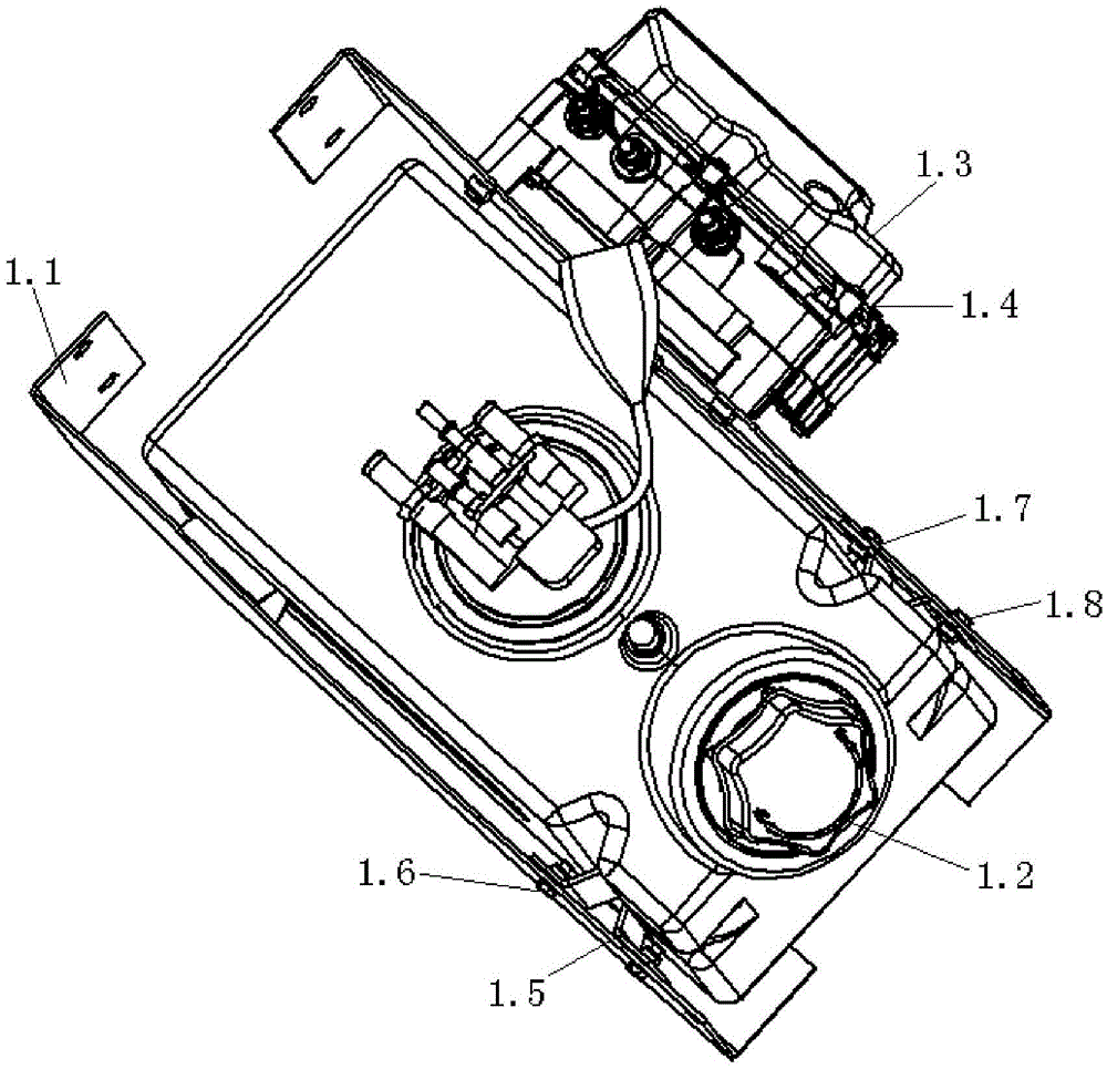
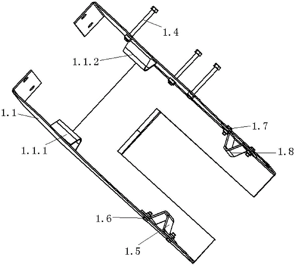
A urea tank bracket

A technology for urea tanks and side baffles, applied in the direction of noise reduction devices, engine components, machines/engines, etc., can solve the problems of urea tank 1.2 interference, poor structural rigidity, and difficult assembly, so as to achieve easy assembly, improve assembly freedom, The effect of avoiding interference

Active Publication Date: 2016-06-22
ANHUI JIANGHUAI AUTOMOBILE GRP CORP LTD
View PDF3 Cites 0 Cited by
  • Summary
  • Abstract
  • Description
  • Claims
  • Application Information

AI Technical Summary

Problems solved by technology

[0005] 1) After the fastening component 1.4 is tightened, it is easy to interfere with the urea tank 1.2;
[0006] 2) After the fastening component 1.6 is tightened, it is easy to interfere with the urea tank 1.2;
[0007] 3) After the fastening component 1.7 is tightened, it is easy to interfere with the urea tank 1.2;
[0008] 4) The degrees of freedom restricted by the positioning block 1.1.1 and the positioning block 1.1.2 on the urea tank bracket 1.1 overlap with the positioning block 1.5 and the positioning block 1.7, which is easy to cause assembly difficulties;
[0009] 5) The urea tank bracket 1.1 itself has poor structural rigidity and poor reliability

Method used


Image

  • A urea tank bracket
  • A urea tank bracket
  • A urea tank bracket

Examples


Embodiment Construction

[0033] The technical solutions of the present invention are described below through specific examples. The following examples are only exemplary, and can only be used to explain and illustrate the technical solutions of the present invention, and cannot be construed as limitations on the technical solutions of the present invention.

[0034] In this application, the front end refers to the end of the bracket body where the clamp is installed; the outer side refers to the outer side of the outer surface of the two side baffles, and the inner side connected to the bracket body.

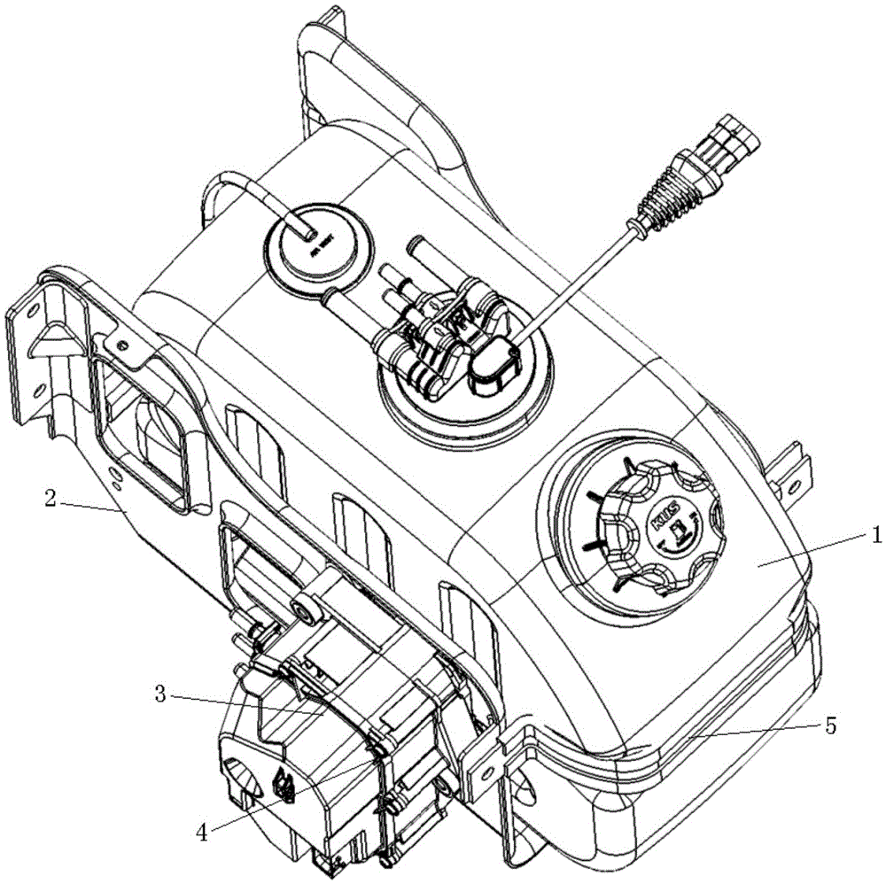
[0035] image 3 It is a schematic diagram of the assembly structure of the urea solution storage system of the present invention. With the upgrading of automobile emission regulations, many vehicles adopt selective catalytic reduction technology to clean exhaust gas. This technology must use a reducing agent, usually urea solution, so the vehicle must have a storage device for the urea solution. The i...


PUM


Abstract

The invention relates to a urea tank bracket, which includes a bracket body, clamps and fasteners; the bracket body includes a bottom plate, two side baffles and a rear baffle rod. The bottom plate is provided with a U-shaped groove to realize the left and right limit of the urea tank; the front and rear limit of the urea tank is realized through the cooperation of the positioning block and the clamp; the up and down limit of the urea tank is realized through the cooperation of the stop rod and the bottom plate. A boss with a threaded hole is arranged on the outer wall of one of the side baffles to prevent the fastener from interfering with the urea tank after passing through the side baffle. The invention effectively avoids the interference between the fastener and the urea tank body, improves the degree of freedom of assembly, increases the strength and rigidity of the bracket, and makes assembly easier and tighter.

Description

technical field [0001] The invention belongs to the technical field of auxiliary support frames for automobile exhaust emission systems, and in particular relates to a urea tank support. Background technique [0002] With the upgrading of automobile emission regulations, many vehicles adopt selective catalytic reduction technology, which must use a reducing agent, usually urea solution, so the vehicle must have a storage device for urea solution. [0003] Existing technologies such as figure 1 and figure 2 As shown, the urea tank 1.2 is used to store the urea solution, the urea tank bracket 1.1 is used to fix the urea tank 1.2, the metering jet pump 1.3 extracts the urea solution from the urea tank 1.2, and presses excess urea solution back into the urea tank 1.2. The urea tank 1.2, the urea tank support 1.1 and the metering jet pump 1.3 together constitute a urea solution storage system. The structure after hiding the urea tank 1.2 and the metering jet pump 1.3 is as fo...

Claims


Application Information

Patent Timeline
Patent Type & Authority Patents(China)
IPC IPC(8): F01N3/28
Inventor 王家华冯东亚陈建辉
Owner ANHUI JIANGHUAI AUTOMOBILE GRP CORP LTD
Why Eureka
Try Eureka