

Synchronizing circuit of flow distributing and collecting valve for two-column gantry lifter
A technology of diverting and collecting valve and lift, which is applied in mechanical equipment, fluid pressure actuating device, servo motor, etc., can solve the problems of the speed and displacement of the hydraulic cylinder rising and falling, which are not easy to synchronize, and achieve simple structure and deviation correction. Powerful, easy-to-manufacture effects
- Summary
- Abstract
- Description
- Claims
- Application Information
AI Technical Summary
Problems solved by technology
Method used
Image

Examples
Embodiment 1
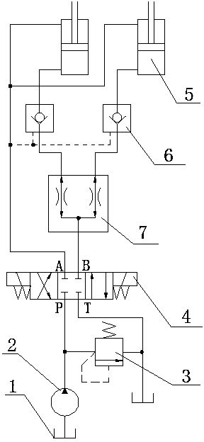
[0017] Such as figure 1 As shown, the synchronous circuit of the diverter and collector valve of the two-column gantry lift includes a fuel tank 1, a hydraulic pump 2, an overflow valve 3, a reversing valve 4, a hydraulic cylinder 5, a hydraulic control check valve 6, and a diverter and collector valve 7. The inlet oil pipe of the hydraulic pump 2 is connected to the oil tank 1, and the outlet oil pipe is connected to the overflow valve 3 and the reversing valve 4 respectively, and the oil return pipes of the overflow valve 3 and the reversing valve 4 are connected to the oil tank 1, and the The diverter and collector valve 7 is connected to the B oil port of the reversing valve 4, and the hydraulic control check valve 6 is connected in series on the oil circuit connecting the hydraulic cylinder 5 and the diverter and collector valve 7. The hydraulic control check valve The control oil circuit of 6 is connected to the A oil port of the reversing valve 4.
[0018] The reversin...
PUM
 Abstract
Description
Claims
Application Information