Unlock instant, AI-driven research and patent intelligence for your innovation.

USB difference receiver in wide common mode input field

A common-mode input and receiver technology, applied in transmission systems, electrical components, etc., can solve problems such as high voltage

Inactive Publication Date: 2014-12-10
CHANGSHA JINGJIA MICROELECTRONICS
View PDF7 Cites 0 Cited by
  • Summary
  • Abstract
  • Description
  • Claims
  • Application Information

AI Technical Summary

Problems solved by technology

For a wide common-mode input range, most amplifiers cannot meet the requirements. Generally, NMOS-type input-to-tube amplifiers have a high common-mode input voltage, while PMOS-type input-to-tube amplifiers have a high common-mode input voltage.

Method used


Image

  • USB difference receiver in wide common mode input field
  • USB difference receiver in wide common mode input field
  • USB difference receiver in wide common mode input field

Examples


Embodiment Construction

[0019] DETAILED DESCRIPTION OF THE PREFERRED EMBODIMENTS The spirit of the present invention will be further described, and the exemplary embodiments and descriptions of the present invention are used to explain the present invention, but should not be regarded as limiting the present invention.

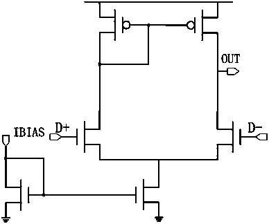
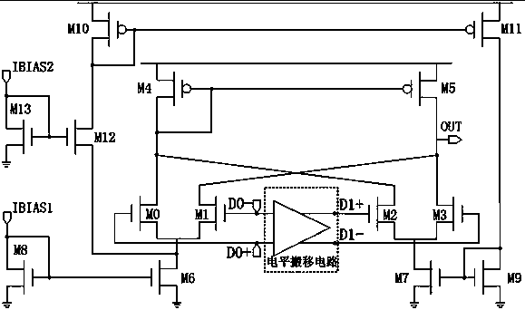
[0020] Compared figure 1 and figure 2 , to address common amplifier structures such as figure 1 The amplifier structure shown) the problem that the common mode input range is narrow, the present invention proposes such as figure 2 The circuit configuration shown. The USB differential receiver circuit with a novel wide common mode input range includes a pair of differential data signals D0+, D0-, which are the input signals of the differential receiver, and the level input range of the differential data signal is common to the differential receiver. The input range of the mode puts forward requirements; the circuit includes two bias currents IBIAS1, IBIAS2 and IBIAS1 current mirr...


PUM


Abstract

The invention discloses a circuit structure for a USB difference receiver in a wide common mode input field. The circuit comprises an input differential signal level removal circuit and a current bias circuit (M 8-M 13); the circuit further comprises amplifiers (M 0-M 7) of two pairs of difference input geminate transistors. According to the circuit structure, the amplifiers of the two pairs of the difference input geminate transistors are connected to the front and the rear of the differential signal level removal circuit respectively, and through the adoption of the self-adapting current bias circuit, the amplifiers can work normally in the wide common mode input field.

Description

technical field [0001] The invention belongs to the field of integrated circuit design, and more specifically relates to the design of a USB differential receiver. Background technique [0002] In the USB physical layer circuit, the differential receiver is responsible for converting the data received by the USB into electrical characteristics that meet the requirements of the USB protocol. For example, the USB protocol stipulates the minimum value of the high voltage and the maximum value of the low level of the signal, and requires the designed circuit to meet the specification requirements. Because USB signals are affected by working voltage, temperature, transmission attenuation, external electromagnetic interference and other conditions during actual work, the protocol requirements are generally strict and must meet the protocol requirements. Among them, the common-mode voltage requirement of the differential signal is 0.8V~2.5V, which is a very wide common-mode input ...

Claims


Application Information

Patent Timeline
Patent Type & Authority Applications(China)
IPC IPC(8): H04B1/16
Inventor 周晓亚
Owner CHANGSHA JINGJIA MICROELECTRONICS