Vane-type pump having a housing, having a displaceable stator, and having a rotor that is rotatable within the stator

A vane pump and stator technology, which is applied to liquid fuel engines, pumps, pump components, etc., can solve the problems of large vane pump size and reduced power supply, and achieve the effect of simple rigidity and improved effective power supply.

Active Publication Date: 2014-12-10
ROBERT BOSCH GMBH
View PDF4 Cites 0 Cited by
  • Summary
  • Abstract
  • Description
  • Claims
  • Application Information

AI Technical Summary

Problems solved by technology

The supply power may be further reduced due to leakage of oil flow, especially at low speeds, which has a serious impact on the operation o...

Method used


Image

  • Vane-type pump having a housing, having a displaceable stator, and having a rotor that is rotatable within the stator
  • Vane-type pump having a housing, having a displaceable stator, and having a rotor that is rotatable within the stator
  • Vane-type pump having a housing, having a displaceable stator, and having a rotor that is rotatable within the stator

Examples


Embodiment Construction

[0017] In all the figures, also in the different embodiments, functionally equivalent elements and dimensions are provided with the same reference numerals.

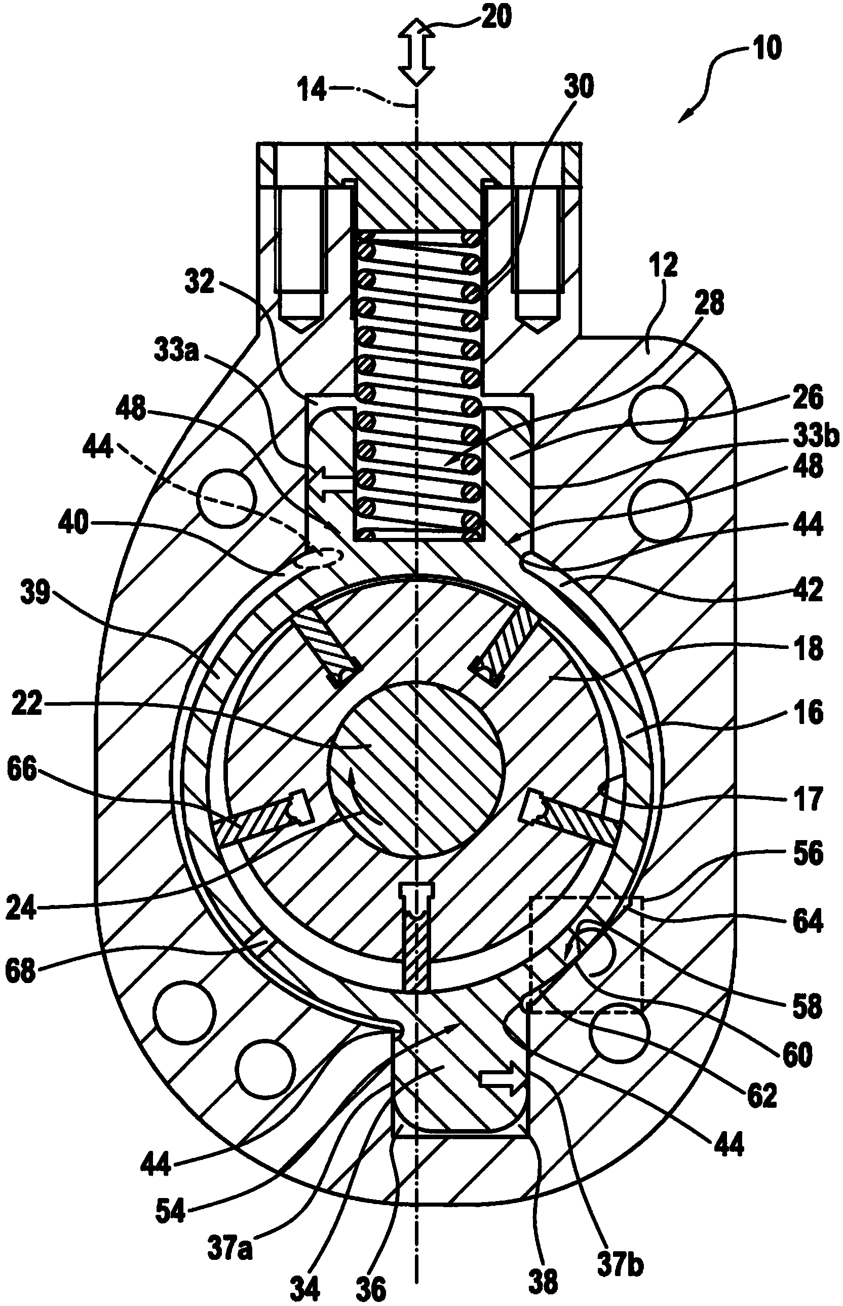
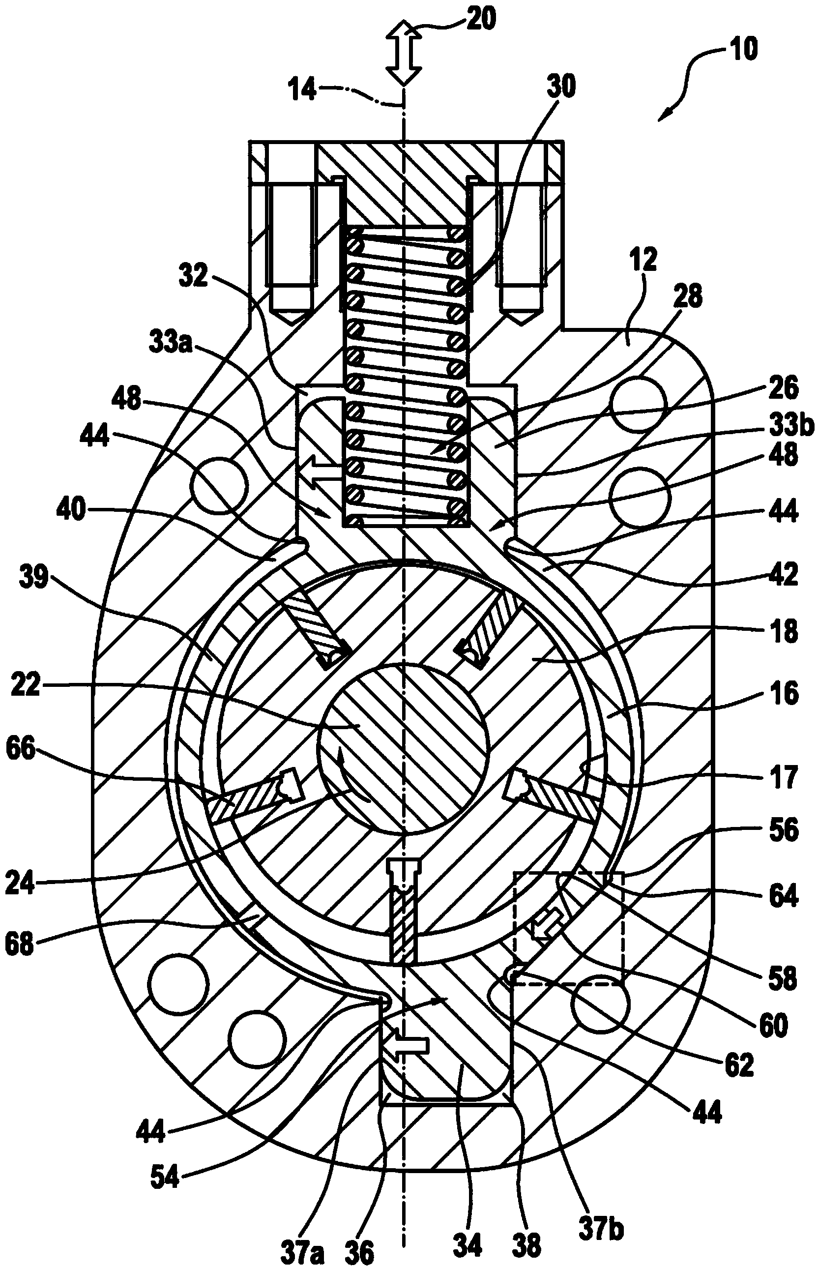
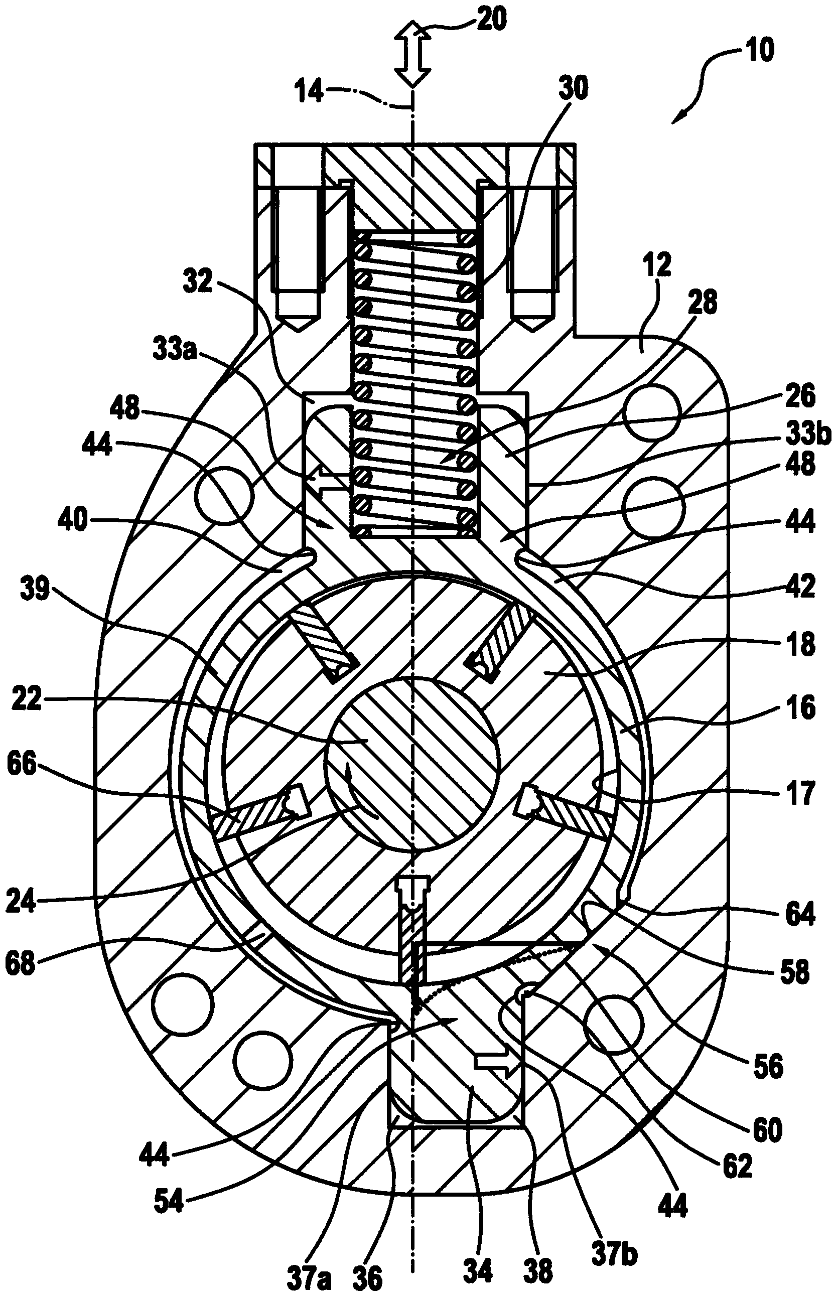
[0018] figure 1 A sectional view perpendicular to the drive shaft of the first embodiment of the vane pump 10 is shown. The vane pump 10 is, for example, a fuel pump of an internal combustion engine (not shown). The vane pump 10 comprises a housing 12 , a stator 16 movably guided in the housing 12 parallel to the axis 14 , and a rotor 18 accommodated in a recess (wall surface 17 ) of the stator 16 . The direction of movement of the stator 16 in the housing 12 is indicated by a double-headed arrow 20 . The rotor 18 is arranged perpendicular to the drawing on a rotational axis 22 , which is rotatably mounted in the housing 12 in a manner not shown, so that it can be rotated in the clockwise direction corresponding to the arrow 24 . The direction of movement 20 and the axis of rotation 22 are thus perpendicular to each o...


PUM


Abstract

The invention relates to a vane-type pump (10) having a housing (12), having a displaceable stator (16), and having a rotor (18) that is rotatable within the stator (16), wherein the stator (16) is displaceable in the housing (12) in a direction perpendicular to a rotary axle (22) of the rotor (18) and, in the process, is guided in a fluid-tight manner in the housing (12) at at least one point. According to invention, a contact region (56) is formed between the stator (16) and the housing (12), wherein the stator (16), in one end position, is loaded against a contact section (60) of the housing (12), and wherein the contact region (56) is designed, and/or the contact section (60) arranged is relative to the stator (16), such that, as a result, a force is generated that acts on the stator (16) transversely to the displacement direction (20) and/or an additional torque is generated that acts on the stator (16) around the rotary axle (22).

Description

technical field [0001] The invention relates to a vane pump according to the preamble of claim 1 . Background technique [0002] Vane pumps are known on the market, such vane pumps are used, for example, as fuel supply pumps in fuel systems of internal combustion engines. In particular, the vane pump can be designed such that its power supply can be adjusted mechanically. For mechanically driven vane pumps, the maximum delivered power depends on the rotational speed of the internal combustion engine. Therefore, at low speeds, such as when the internal combustion engine or the vehicle has just been started, the supplied power is rather low. Leakage of oil flow may further reduce the supply power, especially at low speeds, which has a serious impact on the operation of the vane pump. In order to solve this problem, it is known that the fuel supply pump and thus the vane pump is oversized with respect to its power. Contents of the invention [0003] The problem to be solv...

Claims


Application Information

Patent Timeline
IPC IPC(8): F01C21/10F04C2/344F04C14/22F04C15/00
CPCF04C15/0042F04C14/223F01C21/102F04C2/3442F01C21/106F04C15/0034
Inventor A·克尔纳B·莱布斯莱W·布劳恩
Owner ROBERT BOSCH GMBH
Why Eureka
Try Eureka