Voice connector

A connector and voice technology, applied in the direction of connection, parts and electrical components of the connection device, etc., can solve the problems of wrong signal, plug reception, etc., and achieve the effect of avoiding wrong signal

Inactive Publication Date: 2014-12-17
LUXSHARE PRECISION INDKUNSHAN +1
View PDF8 Cites 1 Cited by
  • Summary
  • Abstract
  • Description
  • Claims
  • Application Information

AI Technical Summary

Problems solved by technology

[0002] Voice connectors are widely used in electronic products such as mobile phones and computers. Existing voice connectors are usually provided with switches to provide detection signals, such as a voice connector disclosed in Chinese Patent Announcement No. 2523077. The connector includes an insulating body, a number of signal terminals accommodated in the insulating body and a switch. The insulating body is provided with an insertion hole for receiving a plug. Each signal terminal is provided with a contact portion extending into the insertion hole and extending out of the insulating body. The switch includes a fixed terminal and a movable terminal. The movable terminal is provided with a butt joint protruding into the insertion hole and an abutment portion extending backward from the butt joint to abut against the fixed terminal. The butt joint is located at At the rear of the contact part of the signal terminal, when the external voice plug is inserted into the socket hole, it first elastically contacts the contact part of each signal terminal, and as the plug continues to be inserted, the plug pushes against the docking part of the movable terminal, prompting the contact The connection part is disconnected from the fixed terminal to realize the function of detection. However, before each signal terminal touches the predetermined position of the plug, the switch has completed the switching from the closed state to the open state, resulting in the plug receiving an error signal instantaneously.

Method used


Image

  • Voice connector
  • Voice connector
  • Voice connector

Examples


Embodiment Construction

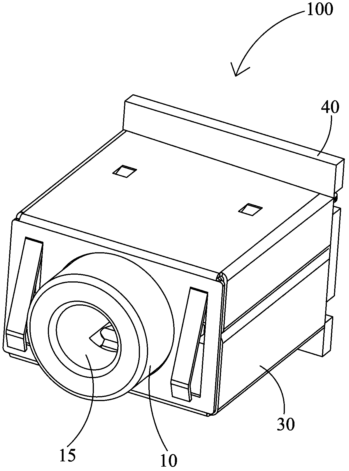
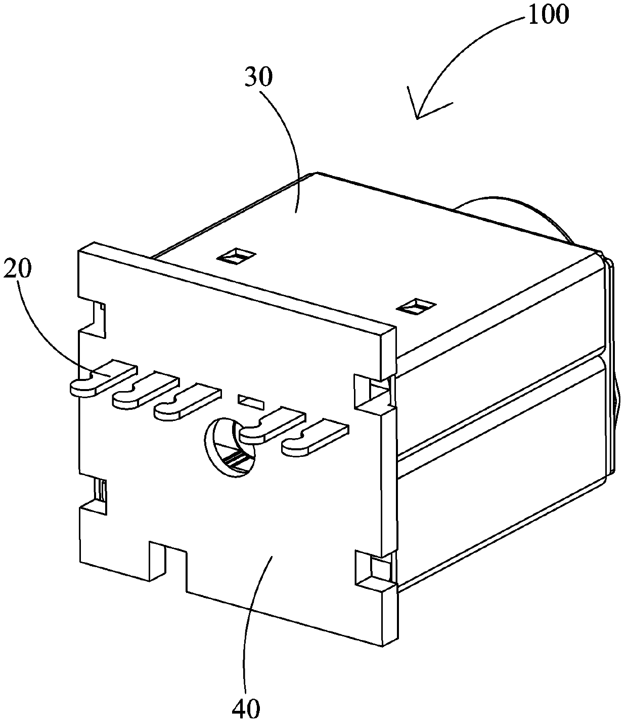
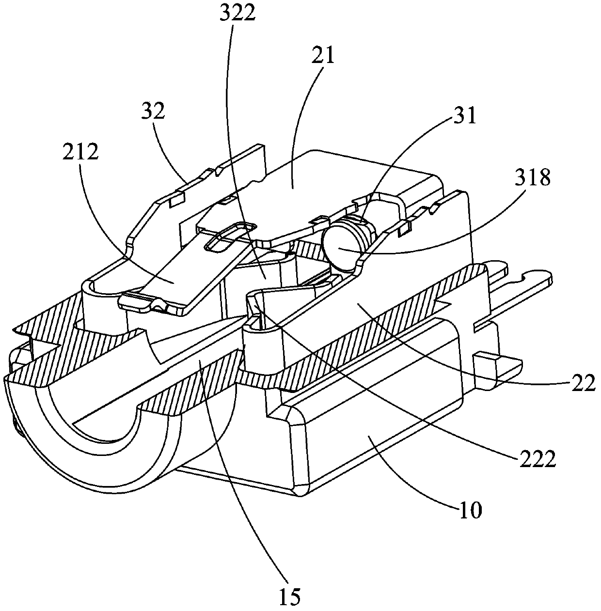
[0012] see Figure 1 to Figure 5 As shown, the voice connector 100 of the present invention includes an insulating body 10, a plurality of conductive terminals 20 accommodated in the insulating body 10, a switch, a metal shell 30 covering the insulating body 10, and a cover plate assembled forwardly at the rear end of the insulating body 10 40.

[0013] The insulating body 10 includes a main body 11 and a docking portion 12 protruding forward from the main body 11. An insertion hole 15 runs through the main body 11 and the docking portion 12 front and rear for receiving a plug (not shown). The main body 11 includes Surrounding the top wall 16, bottom wall 17 and side walls 18 outside the insertion hole 15, the top wall 16 is provided with a first receiving groove 161, and the side wall 18 is provided with a second receiving groove 182 and is located in the second receiving groove. The third storage groove 183 inside 182, the other side wall 18 offers a sixth storage groove 18...


PUM


Abstract

The invention relates to a voice connector. The voice connector comprises an insulation body, a plurality of conductive terminals and a switch, the conductive terminals are contained in the insulation body, the insulation body is provided with an insertion hole extending longitudinally, each conductive terminal comprises a contact portion protrudingly extending into the insertion hole and a weld pin extending out of the insulation body, and the switch comprises a moving terminal and a fixed terminal. The moving terminal comprises a butting portion extending into the insertion hole and a first welding portion extending out of the insulation body, the fixed terminal comprises a lapping portion and a second welding portion extending out of the insulation body, the butting portion is positioned behind the contact portions of the conductive terminals, and the butting portion is longitudinally aligned to the lapping portion to contact with or disconnect with the lapping portion. On-off switching of the switch is finished after the contact portions of the conductive terminals contact with preset positions of a plug, and accordingly instant generation of false signals can be avoided, and the plug can receive accurate signals.

Description

technical field [0001] The invention relates to a voice connector, in particular to a voice connector with a switch. Background technique [0002] Voice connectors are widely used in electronic products such as mobile phones and computers. Existing voice connectors are usually provided with switches to provide detection signals, such as a voice connector disclosed in Chinese Patent Announcement No. 2523077. The connector includes an insulating body, a number of signal terminals accommodated in the insulating body and a switch. The insulating body is provided with an insertion hole for receiving a plug. Each signal terminal is provided with a contact portion extending into the insertion hole and extending out of the insulating body. The switch includes a fixed terminal and a movable terminal. The movable terminal is provided with a butt joint protruding into the insertion hole and an abutment portion extending backward from the butt joint to abut against the fixed terminal. T...

Claims


Application Information

Patent Timeline
Patent Type & Authority Applications(China)
IPC IPC(8): H01R13/703
Inventor 张光卿冉海
Owner LUXSHARE PRECISION INDKUNSHAN
Why Eureka
Try Eureka