Cascade bus signal receiving circuit and control system thereof
A bus signal and receiving circuit technology, applied in the electronic field, can solve problems such as wall or ground damage, control signals that cannot be correctly analyzed, and adverse effects of home equipment control, so as to avoid parsing out wrong signals, accurately control, and facilitate control. Effect
- Summary
- Abstract
- Description
- Claims
- Application Information
AI Technical Summary
Problems solved by technology
Method used
Image

Examples
Embodiment 1
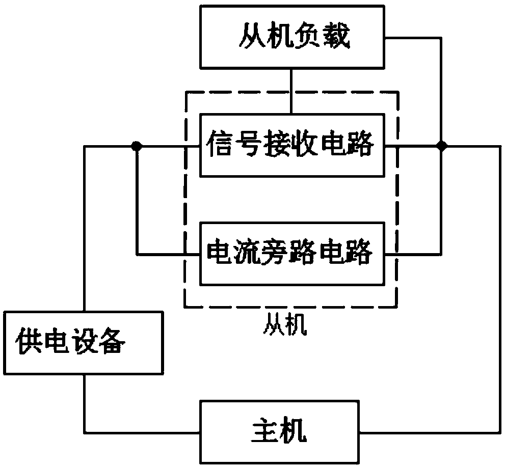
[0028] A cascaded bus signal receiving circuit is arranged in a power supply cable, such as Figure 4As shown, it includes a first diode D1, a signal receiving module, a processor and a fourth capacitor C4; the anode of the first diode D1 is electrically connected to the first terminal of the power supply device; the signal receiving modules are respectively It is electrically connected to the anode of the first diode D1, the cathode of the first diode D1, the processor and the host, and the joint point of the signal receiving module and the processor is electrically connected to a 3.3V power supply; the signal receiving module, It is used to detect the voltage difference between the anode and the cathode of the first diode D1 to analyze the control signal sent by the host and send the control signal to the processor; the processor is electrically connected to the slave load, it should be understood What is more, the slave load is household equipment; the processor is used to ...
Embodiment 2
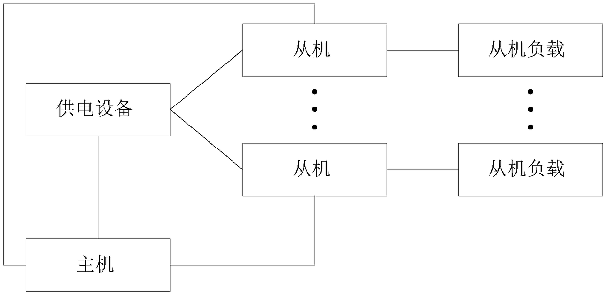
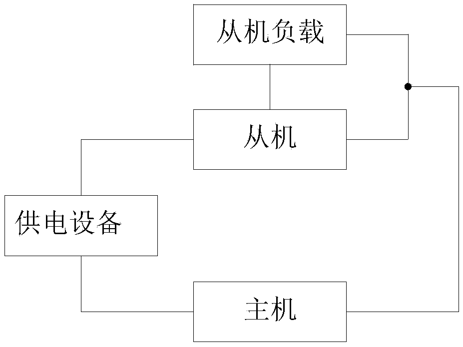
[0035] A cascaded bus control system such as Figures 1 to 4 As shown, it includes a power supply device, a host, at least one slave and at least one slave load, and the slave and the slave load are set in one-to-one correspondence; the first terminals of the power supply device are respectively electrically connected to each slave, so The second terminal of the power supply device is electrically connected to the host, and the host is electrically connected to each slave and each slave load; each slave is electrically connected to a slave load; the power supply is used to pass The power supply cable supplies power to the host, each of the slaves, and each of the slave loads; the host is used to supply power to each of the slaves through the power supply cable between the slave and the host The slave sends a control signal; each of the slaves is used to control the load of the connected slave according to the control signal sent by the master; each of the slaves includes the f...
PUM
 Abstract
Description
Claims
Application Information