Steel plate drilling device

A drill and steel plate technology, applied in the direction of boring/drilling, drilling/drilling equipment, large fixed members, etc., can solve the problems of increasing the difficulty of adjusting the position, affecting work efficiency, etc., to increase safety, Increased convenience and beneficial control effects

Inactive Publication Date: 2019-06-04
李琦
View PDF0 Cites 0 Cited by
  • Summary
  • Abstract
  • Description
  • Claims
  • Application Information

AI Technical Summary

Problems solved by technology

[0002] When the magnetic rotary drill is used to drill holes on the vertical steel plate, due to the gravity of the electric magnetic drill itself, the operator increases the difficulty of adjusting the position, which in turn affects the work efficiency

Method used


Image

  • Steel plate drilling device
  • Steel plate drilling device

Examples


Embodiment Construction

[0009] Preferred embodiments of the invention are described below in conjunction with the accompanying drawings:

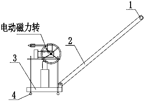
[0010] Such as figure 1 As shown, a steel plate drill includes a hand push rod 1, a connecting rod 2 connected to the hand push rod 1, a base 3 connected to one end of the connecting rod 2 carrying a hydraulic jack, and four A supporting wheel 4 with a locking device, a positioning bracket is arranged on the supporting wheel 4, a bearing tray that can slide up and down relative to the positioning bracket is arranged on the top of the base 3 and on the positioning bracket, and the bottom of the supporting tray is movably connected with a hydraulic jack. An electric magnetic drill is fixed laterally on the upper part of the loading tray.

[0011] The principle of the present invention: the present invention can slide the base on the positioning bracket through the hydraulic jack, and adjust the height position of the electric magnetic drill; the body body can be ad...


PUM


Abstract

The invention discloses a steel plate drilling device for a hospital. The steel plate drilling device comprises a hand pushing rod, a connecting rod, a base and supporting wheels, wherein the connecting rod is connected with the hand pushing rod, the base which is connected with one end of the connecting rod and is provided with a hydraulic jack, four supporting wheels with locking devices are arranged at the bottom of the base, a positioning support is arranged on the supporting wheels, a bearing tray capable of sliding up and down relative to the positioning support is arranged above the base and on the positioning support, the bottom of the bearing tray is movably connected with the hydraulic jack, and an electric magnetic drill is transversely and fixedly arranged at the upper part ofthe bearing tray. The steel plate drilling device is simple in structure and convenient to operate.

Description

technical field [0001] The invention relates to a steel plate drill. Background technique [0002] When the magnetic rotary drill is used to drill holes on the vertical steel plate, due to the gravity of the electric magnetic drill itself, the operator increases the difficulty of adjusting the position, which in turn affects the work efficiency. Contents of the invention [0003] The purpose of the present invention is to provide a simple, labor-saving, and easy-to-operate steel plate drill aiming at the problems existing in the prior art. [0004] The technical scheme that the present invention adopts for realizing the above object is: [0005] A steel plate drill, comprising a hand push rod, a connecting rod connected to the hand push rod, a base connected to one end of the connecting rod and carrying a hydraulic jack, four support wheels with locking devices are arranged at the bottom of the base, The support wheel is provided with a positioning bracket, and above the...

Claims


Application Information

Patent Timeline
IPC IPC(8): B23B41/00B23Q1/25
Inventor 李琦
Owner 李琦
Why Eureka
Try Eureka