Flue gas purifying and stabilizing device of flat glass melting furnace

A flue gas purification, flat glass technology, applied in chemical instruments and methods, dispersed particle separation, separation methods and other directions, can solve the problems of large denitration catalyst scouring, affecting dust removal efficiency, difficult control of waste heat boilers, etc. The effect of increasing the effect

Inactive Publication Date: 2016-03-16
(CNBM) BENGBU DESIGN & RES INST FOR GLASS IND CO LTD
View PDF7 Cites 0 Cited by
  • Summary
  • Abstract
  • Description
  • Claims
  • Application Information

AI Technical Summary

Problems solved by technology

These purification methods all set the purification device at the back end of the glass melting furnace. Due to the structural characteristics of the melting furnace, when the glass is burned and melted, the fire needs to be changed at intervals, usually every 20 minutes or so. The amount of flue gas decreases sharply, and then increases sharply, showing regular fluctuations; it is precisely because of this fluctuation that the control of flue gas purification is difficult, which is manifested in: 1. The heat absorption of the heat exchanger of the waste heat utilization system changes with time 2. For the electrostatic precipitator system, the change of the flue gas flow rate causes the change of the gas flow rate in the electrostatic precipitator. For the initial flow rate of the electrostatic precipitator design, the fluctuation 3. For out of stock, the ammonia injection device of the denitrification reactor needs to change with the change of flue gas flow, but the fact is that it is difficult to do this; Fourth, the change of flue gas flow has different degrees of impact on wet desulfurization and dry / semi-dry desulfurization; terminal purification control

Method used


Image

  • Flue gas purifying and stabilizing device of flat glass melting furnace

Examples


Embodiment Construction

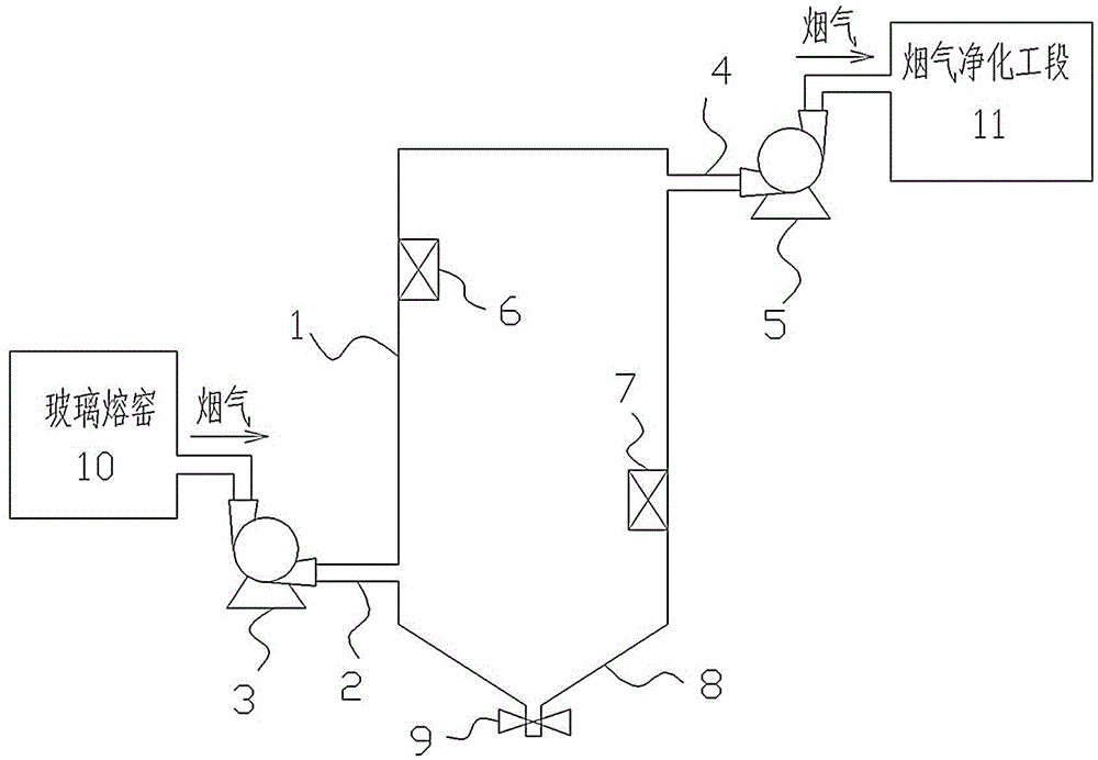
[0010] Such as figure 1 As shown, the present invention provides a flue gas purification and stabilizing device for a flat glass melting furnace, which includes a gas bin 1 whose volume is the volume of flue gas produced in one fire change cycle of the glass melting furnace; the gas bin 1 passes through the smoke inlet pipe 2 It is connected with the smoke outlet of the glass melting furnace 10, and the gas chamber 1 is connected with the flue gas purification section 11 through the smoke outlet pipe 4; The smoke outlet fan 5 is provided on the pipeline; the inner wall of the gas chamber 1 is provided with a first circulation fan 6 and a second circulation fan 7, and the first circulation fan 6 and the second circulation fan 7 are arranged alternately on the upper part of the inner wall of the gas chamber 1 And the lower part; the bottom of the gas chamber 1 is also provided with an ash hopper 8, and the bottom of the ash hopper 8 is provided with a valve 9.

[0011] Before t...


PUM


Abstract

The invention discloses a flue gas purifying and stabilizing device of a flat glass melting furnace. The device comprises a gas chamber, and the volume of the gas chamber is equal to that of flue gas, which is generated during the whole reversal interval of a flat glass melting furnace. The gas chamber is communicated with the flue gas outlet of the flat glass melting furnace through a flue gas inlet pipe. The gas chamber is communicated with a flue gas purifying section through a flue gas outlet pipe. The pipeline of the flue gas inlet pipe is provided with a flue gas inlet induced draft fan, and the pipeline of the flue gas outlet pipe is provided with a flue gas outlet induced draft fan. A circulating fan is arranged on the inner wall of the gas chamber. The bottom of the gas chamber is provided with an ash bucket. The bottom of the ash bucket is provided with a valve. The flue gas discharged from the flat glass melting furnace enters the gas chamber before entering the flue gas purifying section, because the volume of the gas chamber is equal to the volume of flue gas generated in a whole reversal interval, the gas chamber can fully buffer the flue gas, flue gas becomes stable in the gas chamber, then the flue gas is delivered to the flue gas purifying section at a stable flowing speed; thus the flue gas purification can be well controlled, and the flue gas purification effect is improved.

Description

technical field [0001] The invention relates to the technical field of flue gas purification, in particular to a flue gas purification and stabilizing device for a flat glass melting furnace. Background technique [0002] The flat glass industry is one of the key industrial pollution control industries in my country. In recent years, the output of flat glass in my country has been increasing year by year, and the total amount of air pollutants has also increased year by year. Air pollutants mainly include particulate matter, sulfur dioxide, and nitrogen oxides. [0003] At present, the methods for purifying glass furnace flue gas in the flat glass industry mainly include dust removal, desulfurization and denitrification. Dust removal is generally divided into bag type dust removal, electric dust removal and wet dust removal; Semi-dry desulfurization, etc.; and denitrification can be divided into SCR denitrification and SNCR denitrification processes. These purification met...

Claims


Application Information

Patent Timeline
IPC IPC(8): B01D45/02
CPCB01D45/02
Inventor 肖俊清陆少锋
Owner (CNBM) BENGBU DESIGN & RES INST FOR GLASS IND CO LTD
Why Eureka
Try Eureka