A method that can increase the yield of inductive back film processing

A technology of inductance and back film, which is applied in the direction of inductance/transformer/magnet manufacturing, circuits, electrical components, etc., and can solve problems such as increased processing or manufacturing costs

Active Publication Date: 2016-09-28
TAI TECH ADVANCED ELECTRONICS CO LTD
View PDF7 Cites 0 Cited by
  • Summary
  • Abstract
  • Description
  • Claims
  • Application Information

AI Technical Summary

Problems solved by technology

[0003] see figure 2 , image 3 As shown, although the existing inductance back film processing method can achieve the purpose of forming the back film 20 on the inductance 1, it is necessary to use a glue dispenser to dispense glue in the holes 21 of the back film belt 2 in sequence, and then place the The inductance 1 to be processed is placed in the hole 21. Since this kind of operation method can only complete the dispensing of a single hole 21 at a time, even if it is all done by mechanical automation, there are still inherent limitations and limits in terms of production capacity; in addition, After the inductor 1 finishes the processing of the back film 20, the back film tape 2 must be destroyed before the inductor 1 can be taken out, that is, the back film tape 2 is a consumable material, which will cause an increase in processing or manufacturing costs. Therefore, how to develop A processing method for inductive back film that can increase production capacity and reduce costs has become a technical topic of great urgency and practical value

Method used


Image

  • A method that can increase the yield of inductive back film processing
  • A method that can increase the yield of inductive back film processing
  • A method that can increase the yield of inductive back film processing

Examples


Embodiment Construction

[0045] see Figure 4 As shown, the present invention provides a kind of method that can improve the processing yield of inductive back film, and its step comprises:

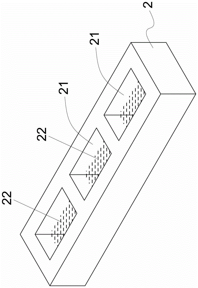
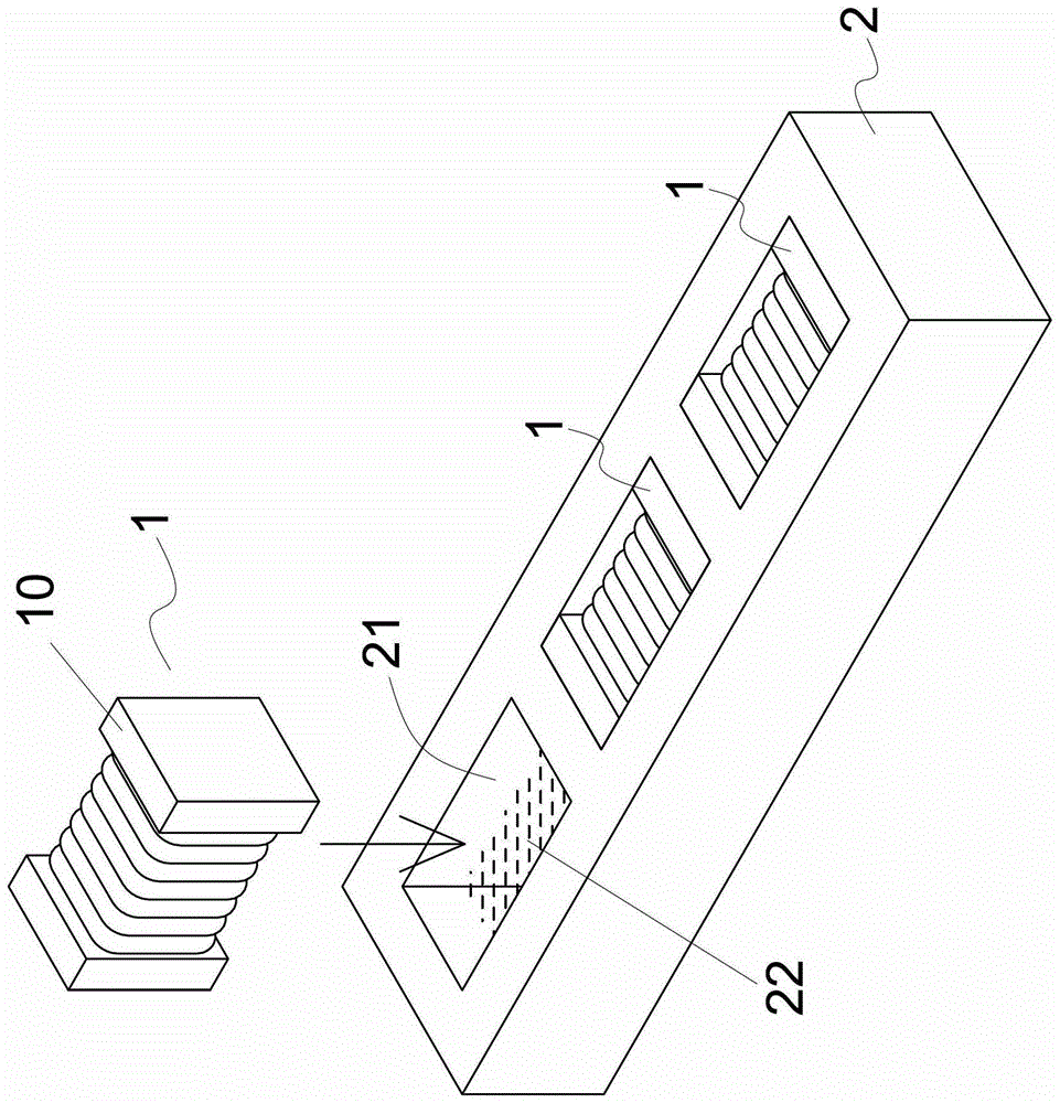
[0046] Material preparation step 3, please refer to Figure 5 As shown, the material preparation step 3 is to prepare a first material plate 31 and the inductor 8 to be processed, wherein the first material plate 31 is provided with a plurality of first holes 311 corresponding to the size of each inductor 8, the first material plate 31 A material plate 31 can be further provided with at least one first positioning hole 312, and a peelable first transparent adhesive film 32 is attached to the bottom of the first material plate 31, please refer to Figure 6 As shown, and the first transparent adhesive film 32 can be provided with at least one second positioning hole 321 corresponding to the position and size of the first positioning hole 312, in addition, in this embodiment, the first material plate 31 is more Sp...


PUM


Abstract

A method capable of improving the processing output of an inductance back film, the steps comprising a material preparation step of preparing a first material plate and inductors to be processed; a filling step of placing each inductor in each first hole of the first material plate; In the printing step, a screen printing machine is used to fill the first holes of the first material plate with UV glue printing; in the combined positioning step, the first material plate is placed on a bottom plate, and a second material plate is placed on the Above the first material plate, finally, place an upper cover plate above the second material plate; in the curing step, use a UV lamp to irradiate the UV glue, so that the UV glue can be cured and molded on the inductor, and the obtained Complete the inductance of the back film processing; with the help of the printing step of the present invention, a large number of gluing operations can be completed at one time by using the screen printing method, and at the same time, the subsequent fixture can be quickly completed with the help of the combined positioning step and curing step Combination and back film curing and shaping action, and then the present invention can achieve the effect of greatly improving production capacity.

Description

technical field [0001] The invention relates to a method for processing an inductance back film, in particular to a method capable of increasing the processing output of an inductance back film. Background technique [0002] see figure 1 As shown, the general inductance 1 is not completely flat because the shape of the iron core 10, so when the product is going to be subjected to SMT (Surface Mount Technology, surface mount technology) operations, in order to facilitate machine suction, the inductance 1 is usually placed without the iron core 10 One side of the electrode terminal is provided with a flat back film 20, please refer to figure 2 As shown, the current industry method for forming the back film 20 on the inductor 1 is mainly to arrange a back film belt 2 on the working area of ​​the dispenser, wherein the back film belt 2 is provided with several Holes 21 with corresponding sizes, and then the glue dispenser sequentially injects UV glue 22 (that is, ultraviolet ...

Claims


Application Information

Patent Timeline
Patent Type & Authority Patents(China)
IPC IPC(8): H01F41/00
Inventor 谢明谚谢清吉
Owner TAI TECH ADVANCED ELECTRONICS CO LTD
Why Eureka
Try Eureka