AI technical title is built by Patsnap AI team. It summarizes the technical point description of the patent document.
A fluid distributor and flow channel technology, applied in the field of fuel cells/flow batteries, can solve the problems of not being able to evenly distribute a gas, complex structure, difficult to replace, etc., and achieve the effects of simple structure, low cost, and easy maintenance.
Inactive Publication Date: 2014-12-24
苏州象雄测控技术有限公司
View PDF9 Cites 2 Cited by
Summary
Abstract
Description
Claims
Application Information
AI Technical Summary
This helps you quickly interpret patents by identifying the three key elements:
Problems solved by technology
Method used
Benefits of technology
Problems solved by technology
[0003] In the above-mentioned existing technologies, none of them can achieve an average distribution of one gas into N stocks (N≥2). They are all technologies that uniformly flow some gases without distribution, and have complex structures, poor versatility, and are not easy to replace. and other shortcomings
Method used
Image
Click on the blue label to locate the original text in one second.
Reading with bidirectional positioning of images and text.
Examples
Embodiment 1
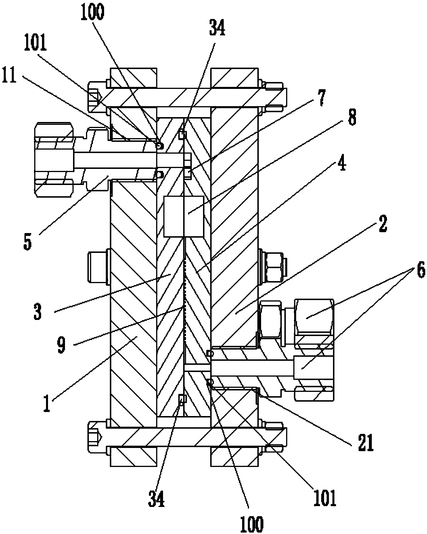
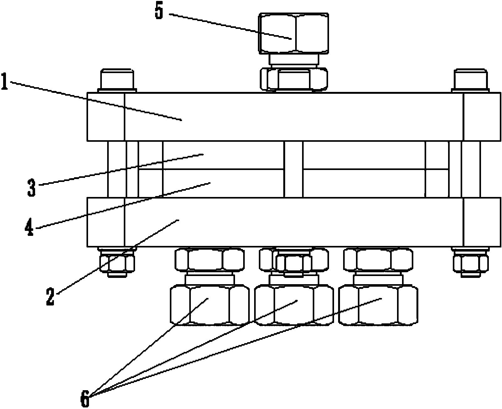
[0034] Embodiment one: if Figure 1 to Figure 5 shown.
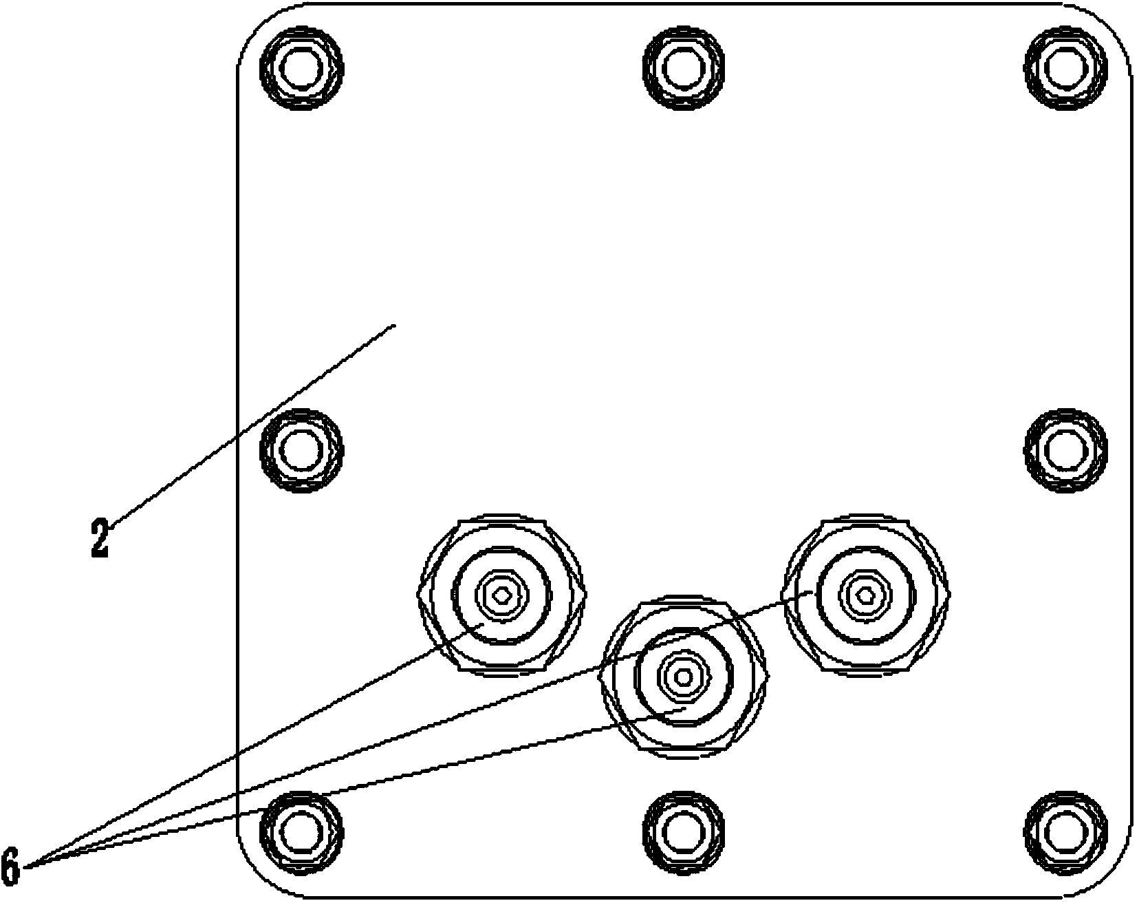
[0035] A fluid distributor, comprising an inlet end plate 1, an outlet end plate 2, a flow channel cover plate 3, a flow channel groove plate 4, an inlet joint 5 and several outlet joints 6,
[0036] An inlet joint hole 11 is opened on the inlet end plate 1, and the inlet joint hole 11 matches the inlet joint 5, and the inlet joint 5 is fixedly arranged in the inlet joint hole 11;
[0037] Several outlet joint holes 21 are opened on the outlet end plate 2, and the outlet joint holes 21 are matched with the outlet joints 6, and several outlet joints 6 are fixedly arranged in several outlet joint holes 21;
[0038] An inlet hole 31 and a first equalizing groove 32 are opened on the runner cover plate 3;
[0039] The flow channel plate 4 is provided with a flow channel groove 41, a second flow equalization groove 42, a number of flow distribution structures and a number of outlet holes 44, the flow channel groove 41 is co...
Embodiment 2
[0067] Embodiment 2: as Figure 7 , Figure 8 shown.
[0068] Figure 7 , Figure 8 It is another embodiment of the fluid distributor of the present invention, which includes a base plate 61, a distribution block 62 and a bracket plate 63 fixedly arranged on the base plate 61, a sealing threaded hole 621 is arranged at one end of the distribution block 62, and the inlet joint 64 is arranged on Among the sealing threaded holes, several distributing holes 622 are arranged in the distributing block 62 .
[0069] One end of the joint 65 is connected to the distribution hole 622 in the distribution block 62, the other end is connected to the first transition capillary 66, the other end of the first transition capillary 66 is connected to the elongated capillary 67, and the other end of the elongated capillary 67 is connected to the second transition capillary 68 , the other end of the second transitional capillary 68 is connected to the over-wall joint 69 , and the over-wall jo...
PUM
Abstract
The invention discloses a fluid distributor which comprises an inlet end plate, an outlet end plate, a runner cover plate, a runner trough plate, an inlet joint and an outlet joint, wherein an inlet joint hole is formed in the inlet end plate, and the inlet joint is arranged in the inlet joint hole; an outlet joint hole is formed in the outlet end plate, and the outlet joint is arranged in the outlet joint hole; an inlet hole and a first flow equalizing trough are formed in the runner cover plate,, and a runner trough, a second flow equalizing trough, a flow dividing structure and an outlet hole are formed in the runner trough plate; the inlet end plate, the runner cover plate, the runner trough plate and the outlet end plate are sequentially and fixedly connected to from a runner trough cavity and a flow equalizing trough cavity. The fluid distributor has the advantages of simple structure and good convenience in installation and realizes primary distribution through the one sub-two and two sub-four runner trough. After being aggregated to the flow equalizing troughs, fluid passes through a flow dividing trough to generate great resistance drop. Equal distribution for the fluid is realized, and the precision is larger than 1 percent.
Description
technical field [0001] The invention relates to the field of fuel cells / liquid flow batteries, in particular to a fluid distributor. Background technique [0002] Nowadays, energy storage systems such as fuel cells and liquid flow batteries are more and more widely used, and the fluid distributors used in the energy storage systems are also attracting more and more attention. In the prior art, the patent ZL201010296275.6 "Gas Distributor for Uniform Outgassing" realizes a stream of gas flowing out evenly through the air holes on the connecting arm in the cavity; the gas in ZL201320075736.6 "A Gas Distributor" After passing through 1008 R0.5mm air holes, it can achieve uniform outflow and has anti-corrosion performance; the patent application number 200410055144.3 "gas distributor for reactor" relates to a gas distributor for uniformly introducing gas flow into the reaction device through the inlet; The patent "Gas Distributor" with the application number 200680023843.7 uses...
Claims
Application Information
Patent Timeline
Application Date:The date an application was filed.
Publication Date:The date a patent or application was officially published.
First Publication Date:The earliest publication date of a patent with the same application number.
Issue Date:Publication date of the patent grant document.
PCT Entry Date:The Entry date of PCT National Phase.
Estimated Expiry Date:The statutory expiry date of a patent right according to the Patent Law, and it is the longest term of protection that the patent right can achieve without the termination of the patent right due to other reasons(Term extension factor has been taken into account ).
Invalid Date:Actual expiry date is based on effective date or publication date of legal transaction data of invalid patent.

