
Method and system for powering a vehicle

一种车辆、供能的技术,应用在用于为车辆供能和系统领域,能够解决变压器占用体积等问题

Active Publication Date: 2014-12-24
GENERAL ELECTRIC CO
View PDF7 Cites 0 Cited by
  • Summary
  • Abstract
  • Description
  • Claims
  • Application Information

AI Technical Summary

Problems solved by technology

Additionally, the transformer may take up additional volume in the confined space of the locomotive

Method used


Image

  • Method and system for powering a vehicle
  • Method and system for powering a vehicle
  • Method and system for powering a vehicle

Examples


Embodiment Construction

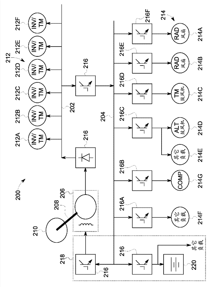
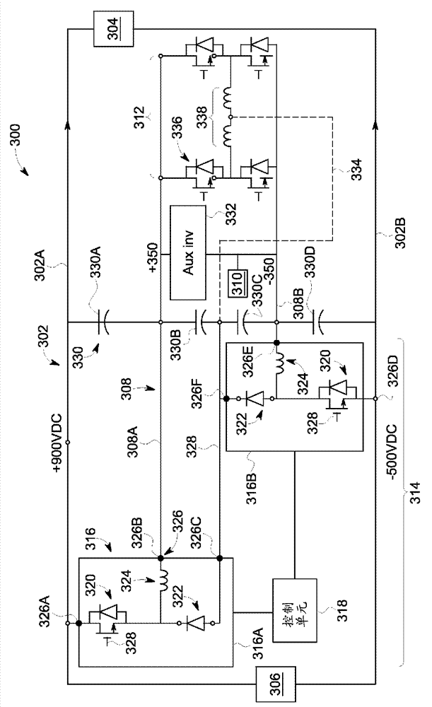
[0016] One or more embodiments of the subject matter of the invention described herein provide a system and method that converts a relatively high voltage transmitted along a traction bus (for example, for powering a traction motor of a vehicle) into A smaller voltage is delivered along the auxiliary bus in order to power non-traction motors (for example, motors that operate at a smaller voltage to perform work that does not involve propelling the vehicle). For example, a voltage of 1400 volts (or another high voltage) can be transferred from one bus to another bus, where the transferred voltage is reduced to 700 volts (or another low voltage) to power non-traction motors. The high voltage on the traction bus can be reduced to a smaller voltage on the auxiliary bus without the need to transmit the high voltage through filters, transformers, etc., and / or the need to modify the non-traction motor to accept the high voltage. For example, a standard (e.g., not modified after purcha...


PUM


Abstract

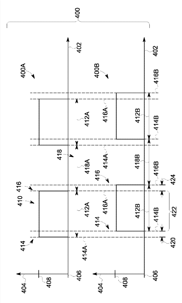
A system for powering a vehicle includes a traction bus, an auxiliary bus, chopper devices, and a control unit. The traction bus is coupled with traction motors of the vehicle to supply a first voltage to power the traction motors. The auxiliary bus is coupled with non-traction motors of the vehicle to supply a different, second voltage to the non-traction motors to. The chopper devices are conductively coupled with both the traction bus and the auxiliary bus to control conduction of the first voltage on the traction bus to the auxiliary bus as the second voltage using first and second duty cycles. The control unit is coupled with the chopper devices to control the first and second duty cycles of the chopper devices, respectively, such that the first voltage on the traction bus is changed (e.g., reduced) to the second voltage on the auxiliary bus.

Description

[0001] Cross references to related applications [0002] This application claims priority of U.S. Provisional Application No. 61 / 624,077 filed on April 13, 2012. The entire disclosure of U.S. Provisional Application No. 61 / 624,077 is incorporated by reference. Background technique [0003] Some known vehicles include traction motors that provide traction for propelling the vehicle and non-traction motors that provide non-traction work for the vehicle. Non-traction motors can operate on compressors, rotating fans, or blowers to cool traction motors, radiators, brakes, etc. or perform other functions. In some known vehicles, such as locomotives, the traction motor operates at a relatively high voltage, such as 1400 volts, to provide sufficient traction for propelling the vehicle. [0004] A single power source can provide current to power traction and non-traction motors. For example, the engine can rotate a shaft connected to an alternator or generator to generate electric current ...

Claims


Application Information

Patent Timeline
Patent Type & Authority Applications(China)
IPC IPC(8): B60L1/00B60L11/02B60L3/00B60L11/12B60L11/18B60L50/10B60L50/15
CPCB60L1/003B60L3/003B60L3/0061B60L2200/10B60L2200/26B60L2200/32B60L2200/40B60L2210/10B60L2210/30B60L2210/40B60L2240/36B60L2260/28B60L50/10B60L50/61B60L58/40Y02T10/62Y02T10/70Y02T10/7072Y02T10/72Y02T90/40
Inventor A. K. 库马
Owner GENERAL ELECTRIC CO
Learn More