Direct type AC power converting apparatus
A technology of power conversion device and DC power supply, which is applied in the direction of converting AC power input to AC power output, output power conversion device, electrical components, etc., which can solve the problem of increasing the impact current of the clamp capacitor and achieve the purpose of reducing voltage pulsation Effect
- Summary
- Abstract
- Description
- Claims
- Application Information
AI Technical Summary
Problems solved by technology
Method used
Image
Examples
no. 1 Embodiment approach
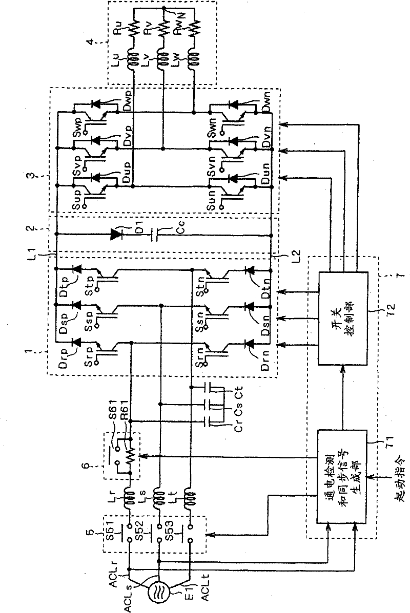
[0073] figure 1 A conceptual configuration of a motor drive device, which is an example of the direct AC power conversion device according to the first embodiment of the present invention, is shown. This motor drive device has: power supply E1, input lines ACLr, ACLs, ACLt, reactors Lr, Ls, Lt, capacitors Cr, Cs, Ct, current source converter 1, DC power lines L1, L2 as output lines, clamp A bit circuit 2, a voltage type inverter 3, a motor 4, a power switch 5, a current limiting circuit 6, and a control unit 7.
[0074] The power source E1 is a multi-phase AC power source, such as a three-phase AC power source, which supplies three-phase AC current to the input lines ACLr, ACLs, ACLt.
[0075] The power switch 5 selects conduction / non-conduction of the input lines ACLr, ACLs, ACLt. More specifically, the power switch 5 has switches S51 to S53. Switches S51 to S53 are relays, for example, and are provided on respective ones of input lines ACLr, ACLs, and ACLt.
[0076] Eac...
no. 2 Embodiment approach
[0124] Figure 8 A conceptual configuration of a motor drive device that is an example of the direct AC power conversion device according to the second embodiment is shown. The conceptual configuration of this motor drive device is the same as that of the first embodiment except for the current limiting circuit 6 . And, clamp circuit 2 can be figure 1 the form shown.
[0125] The current limiting circuit 6 has auxiliary switches S61-S63 and resistors R61-R63. Resistors R61 to R63 are connected in series with reactors Lr, Ls, and Lt to input lines ACLr, ACLs, and ACLt, respectively. The auxiliary switches S61-S63 are respectively connected in parallel with the resistors R61-R63.
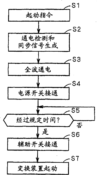
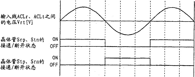
[0126] exist figure 1 In the motor drive device shown, in step S3 , switch control unit 72 connects clamp capacitor Cc in parallel to a capacitor between input line ACLr and input lines ACLs and ACLt provided with resistor R61 . On the other hand, in Figure 8 In the motor driving device show...
no. 3 Embodiment approach
[0134] Figure 12 A conceptual configuration of a motor drive device, which is an example of a direct AC power conversion device according to a third embodiment of the present invention, is shown. The conceptual structure of this motor driving device is in addition to the current limiting circuit 6, and Figure 7 The motor drives shown are the same. In addition, in Figure 12 The post-stage circuit of the clamp circuit 2 is omitted from the figure. Alternatively, clamp circuit 2 can be figure 1 the form shown.
[0135] The current limiting circuit 6 has auxiliary switches S61, S63 and resistors R61-R63. Auxiliary switches S61, S63 are connected in series with reactors Lr, Lt, respectively. Resistors R61 to R63 are provided on respective ones of input lines ACLr, ACLs, and ACLt.
[0136] A group of auxiliary switch S61, reactor Lr is connected to resistor R61, reactor Ls is connected to resistor R62, a group of switch S63, reactor Lt is connected to resistor R63.
[01...
PUM
 Abstract
Description
Claims
Application Information
 - R&D
- Intellectual Property
- Life Sciences
- Materials
- Tech Scout
- Unparalleled Data Quality
- Higher Quality Content
- 60% Fewer Hallucinations
Browse by: Latest US Patents, China's latest patents, Technical Efficacy Thesaurus, Application Domain, Technology Topic, Popular Technical Reports.
© 2025 PatSnap. All rights reserved.Legal|Privacy policy|Modern Slavery Act Transparency Statement|Sitemap|About US| Contact US: help@patsnap.com


