

Liquid crystal display element and liquid crystal display device
A technology of liquid crystal display elements and signal lines, applied in the direction of instruments, nonlinear optics, optics, etc., to achieve the effect of improving display quality and suppressing orientation deviation
- Summary
- Abstract
- Description
- Claims
- Application Information
AI Technical Summary
Problems solved by technology
Method used
Image

Examples
Embodiment approach 1
[0069] (Overview of liquid crystal display element 10)
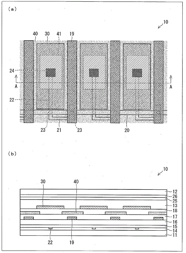
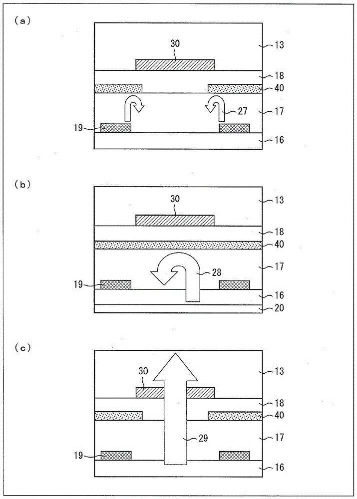
[0070] Side reference figure 1 with 2 Next, the liquid crystal display element 10 according to one embodiment of the present invention will be described. figure 1 (a) is a plan view showing the outline of the liquid crystal display element 10, figure 1 (b) shows figure 1 (a) A cross-sectional view of the outline of the cross section of the line A-A shown. figure 2 (a) is to figure 1 (b) part of the enlarged diagram, figure 2 (b) is the same as figure 1 (a) An enlarged view of the cross section of the line on the scanning line 20 parallel to the line A-A. figure 2 (c) is the same as figure 2 (a) In the same way figure 1 The partially enlarged view of (b) shows a state where the backlight 29 is incident on the liquid crystal layer 13.
[0071] The liquid crystal display element 10 is a VA mode liquid crystal display element which is a type of longitudinal electric field type liquid crystal display element, and uses dot...
Embodiment approach 2
[0137] (Liquid crystal display element 50)
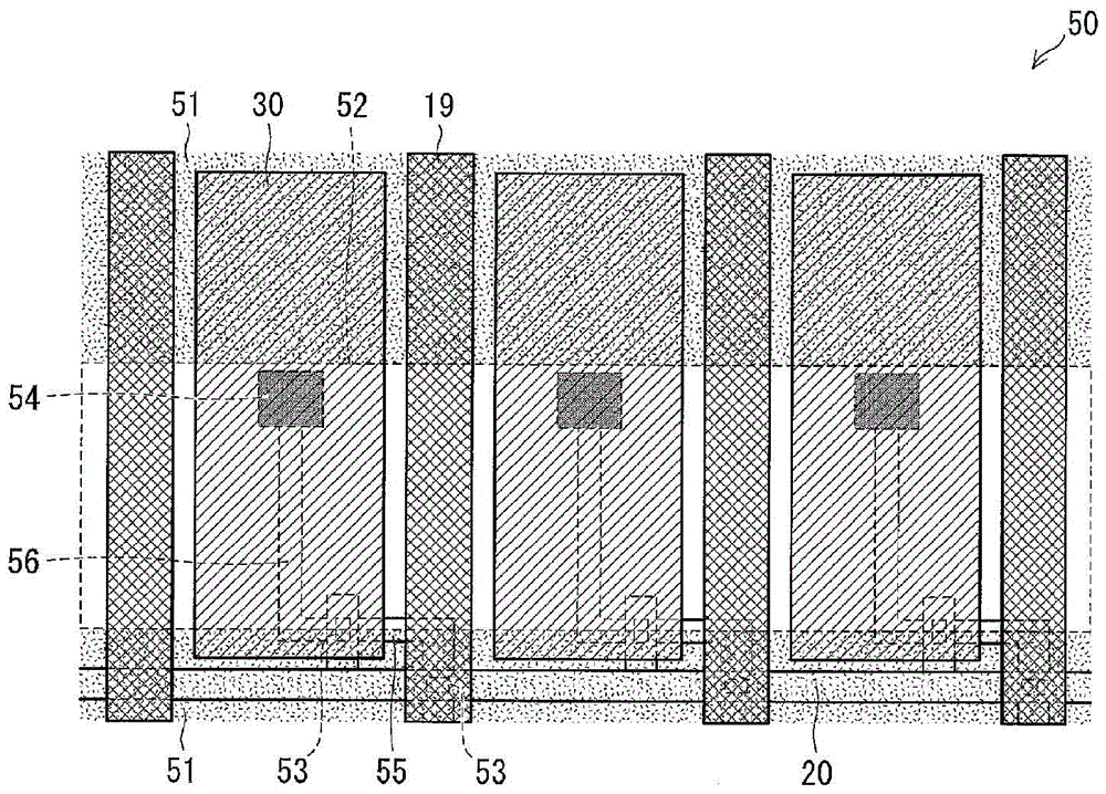
[0138] Side reference image 3 Next, a liquid crystal display element 50 as another embodiment of the present invention will be described. image 3 It is a plan view showing the outline of the liquid crystal display element 50. The liquid crystal display element 50 is different from the liquid crystal display element 10 in the shapes of the common electrode 51 and the TFT 53. Therefore, in this embodiment, the common electrode 51 and the TFT 53 will be described. In addition, the same components as those included in the liquid crystal display element 10 are denoted by the same reference numerals, and the description thereof will be omitted.
[0139] (Common electrode 51)
[0140] The liquid crystal display element 50 is a VA mode liquid crystal display element like the liquid crystal display element 10. However, the liquid crystal display element 10 is driven by dot inversion driving, and the liquid crystal display element 50 is driven ...
Embodiment approach 3
[0152] Side reference Figure 4 A description will be given of a liquid crystal display element 60 as another embodiment of the present invention. The common electrode 61 included in the liquid crystal display element 60 differs from the common electrode 51 included in the liquid crystal display element 50 in the shape of the opening. The shape of the common electrode 51 is rectangular. Therefore, when the length of the common electrode 51 in the direction parallel to the signal line is taken as the width, the width is always constant.
[0153] On the other hand, the width of the common electrode 61 is not constant. The width of the common electrode 61 in the area where the signal line 19 is provided and the peripheral area where the signal line 19 is provided is formed to be larger than the width of the common electrode 61 in the area other than the area.
[0154] Thereby, the common electrode 61 can cover a larger area in the area where the signal line 19 is provided. Therefor...
PUM
 Abstract
Description
Claims
Application Information