Slag fetching device used after slagging smelting and use method thereof

A kind of equipment and slag-making technology, which is applied in the field of slag-taking equipment after slagging and smelting, can solve the problems of polysilicon mixed with slag agent and difficult to separate, and achieve the effects of reducing energy consumption, effectively taking slag and dumping, saving production cycle and cost

Inactive Publication Date: 2014-12-31
QINGDAO NEW ENERGY SOLUTIONS
View PDF2 Cites 0 Cited by
  • Summary
  • Abstract
  • Description
  • Claims
  • Application Information

AI Technical Summary

Problems solved by technology

However, due to the mixing between the two liquid states, the finally poured polysilicon is often mixed with slag agent, which is not easy to separate

Method used


Image

  • Slag fetching device used after slagging smelting and use method thereof

Examples


Embodiment 1

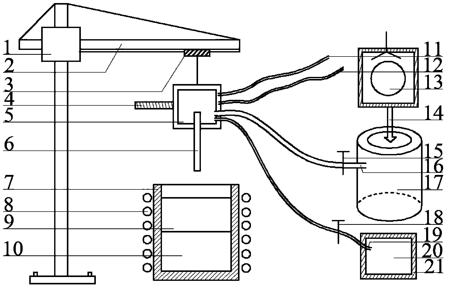
[0024] like figure 1 The shown slag extraction equipment after slag making and smelting includes a cantilever crane 1, a cantilever 2 is fixedly installed on the cantilever crane 1, a wire reel 3 is fixedly installed on the cantilever 2, and the wire reel 3 is suspended and connected with a slag storage device. 5. A closed cavity is formed between the inner wall and the outer wall of the slag storage device 5. The closed cavity is connected with a water inlet pipe 12 and a water outlet pipe 11. The slag storage device 5 is communicated with the vacuum tank 17 through the vacuum bellows 16. It is also communicated with the gas cylinder 21 through the blowing pipe 19, wherein the vacuum tank 17 is connected to the vacuum pump 13 through the connecting pipe 14, the bottom of the slag storage device 5 is communicated with a graphite tube 6, and a graphite crucible 7 is placed at the bottom of the outlet end of the graphite tube 6. An induction coil 8 is wound around the outer wall...

Embodiment 2

[0029] Use the equipment described in Example 1 to pick up the slag:

[0030] The first step of pretreatment: put the silicon material and slag material into the graphite crucible 7, start the power supply of the induction coil 8, and heat the silicon material and the slag material in the graphite crucible 7 to 1500 ° C to completely melt into a molten state to form silicon liquid 10 and slag agent 9, and keep warm at this temperature for 30min;

[0031] The second step is to inflate: control the winding machine 3 to make the slag storage device 5 descend until the bottom end of the graphite tube 6 descends to the bottom of the silicon liquid 10, open the gas valve 18 at this time, and pass the gas 20 into the molten silicon liquid 10, Make the gas 20 fully react with the molten silicon liquid 10;

[0032] The third step is slag extraction treatment: after the inflation process is completed, the gas valve 18 is closed, and the reel 3 is controlled to make the slag storage dev...

Embodiment 3

[0038] Use the equipment described in Example 1 to pick up the slag:

[0039] The first step of pretreatment: put the silicon material and slag material into the graphite crucible 7, start the power supply of the induction coil 8, and heat the silicon material and the slag material in the graphite crucible 7 to 1500 ° C to completely melt into a molten state to form silicon liquid 10 and slag agent 9, and keep warm at this temperature for 50min;

[0040] The second step is to inflate: control the winding machine 3 to make the slag storage device 5 descend until the bottom end of the graphite tube 6 descends to the bottom of the silicon liquid 10, open the gas valve 18 at this time, and pass the gas 20 into the molten silicon liquid 10, Make the gas 20 fully react with the molten silicon liquid 10;

[0041] The third step is slag extraction treatment: after the inflation process is completed, the gas valve 18 is closed, and the reel 3 is controlled to make the slag storage dev...


PUM


Abstract

Belonging to the technical field of metallurgical slagging, the invention in particular relates to a slag fetching device used after slagging smelting and a use method thereof. On the basis of original slagging equipment, a slag storer, a graphite pipe and a vacuum instrument are added. The use method includes: firstly heating a silicon material and slag to a molten state to form a silicon liquid and a slag agent, stopping heating, extending the graphite pipe into the bottom of the silicon liquid, and then filling the silicon liquid with gas; at the end of gas filling, moving the graphite pipe to the surface layer of the slag agent, then performing vacuum pumping to the other end of the graphite pipe by a vacuum tank, letting the slag agent of the upper layer enter the slag storer under the action of pressure difference, simultaneously extending the graphite pipe downward, ensuring the bottom end of the graphite pipe to dip into the slag agent till all the slag agent enters the slag storer, then opening the slag storer and taking the slag agent out. The device provided by the invention has the advantages of convenient reconstruction and installation, and simple operation. The graphite pipe can extract the slag agent cleanly and dump the slag agent, so that the finally purified polysilicon has improved quality and high yield of primary product, and no dust or other garbage can be generated during production. Thus, the device is applicable to industrial mass production.

Description

technical field [0001] The invention belongs to the technical field of metallurgical slag making, and particularly relates to a slag taking device after slag making and smelting and a method for using the same. Background technique [0002] With the development of the world economy and the advancement of the industrialization process, the demand for energy by human beings is increasing day by day. While satisfying its own rapid development, human beings are also facing the crisis of gradually exhausting fossil energy such as coal, oil and natural gas, and cannot avoid the problem of serious environmental pollution. Compared with traditional energy sources, solar power generation has the advantages of being clean, environmentally friendly, safe and convenient, and has sufficient resources. It is a renewable green energy that can effectively alleviate the problems of energy shortage and environmental pollution. Therefore, photovoltaic energy is considered to be the most impor...

Claims


Application Information

Patent Timeline
Patent Type & Authority Applications(China)
IPC IPC(8): C01B33/037
Inventor 顾正张磊
Owner QINGDAO NEW ENERGY SOLUTIONS
Why Eureka
Try Eureka