

High-strength bolt delayed fracture test method and apparatus thereof
A technology for high-strength bolts and delayed fracture, which is applied to measuring devices, using stable tension/pressure to test material strength, instruments, etc., can solve problems such as cumbersome methods and inconvenient mass evaluation tests
Inactive Publication Date: 2014-12-31
BAOSHAN IRON & STEEL CO LTD
View PDF11 Cites 13 Cited by
- Summary
- Abstract
- Description
- Claims
- Application Information
AI Technical Summary
Problems solved by technology
This method is scientific to evaluate the performance of bolts from the perspective of fracture toughness, but this method is cumbersome and inconvenient for large-scale evaluation tests
Method used
View moreImage
Smart ImageViewing Examples

Examples
Embodiment
[0022] The implementation cases of the above equipment can be shown in the following table:
[0023]
Login to View More PUM
 Abstract
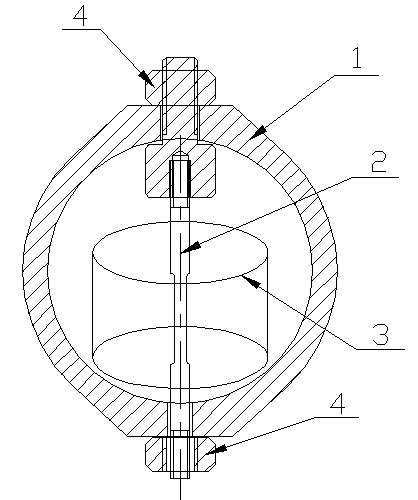
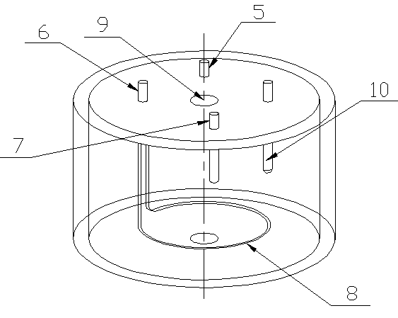
The invention relates to the field of bolt quality control, and especially relates to a method for examining a bolt under simulated actual use conditions, and an apparatus thereof. A high-strength bolt delayed fracture test method comprises the following steps: applying a constant tensile force F to a tested bolt according to the service environment of the tested bolt, simulating the service environment of the tested bolt, and determining the corrosion current density iS under the service environment; and changing the medium solution, the atmosphere and the temperature in an environment container, carrying out acceleration test, determining the corrosion current density iA, calculating to obtain a speed-up ratio, and carrying out acceleration test by using changed parameters to obtain the delay fracture resistance. A high-strength bolt delayed fracture test apparatus comprises a pressure ring and the environment container, the tested bolt is arranged in the environment container, and two ends of the tested bolt are fixedly connected with the pressure ring. The high-strength method and the apparatus thereof can be used for evaluating the delayed fracture resistance of the bolt under the stimulated actual service conditions of the bolt, and predicting the actual service life of the bolt in an acceleration test medium.
Description
technical field [0001] The invention relates to the field of bolt quality control, in particular to a bolt inspection method and device under simulated actual working conditions. Background technique [0002] High-strength bolts used in industrial atmosphere, marine atmosphere and marine environment often face the problem of delayed fracture. Delayed fracture refers to the phenomenon of brittle fracture suddenly occurring after the bolt has been in service for a period of time under stress. Relevant studies have shown that delayed fracture is caused by bolts. The corrosion electrochemical reaction that occurs during service leads to internal hydrogen permeation. In addition, the alternating load and material creep of bolts during service are also important factors that promote delayed fracture. In order to evaluate high-strength bolts, especially high-strength bolts above grade 12.9, research institutions at home and abroad have developed a series of evaluation methods. [...
Claims
Login to View More Application Information
Patent Timeline
 IPC IPC(8): G01N3/08G01N17/02
Inventor杨建强张弛蔡海燕赵社平
OwnerBAOSHAN IRON & STEEL CO LTD