
Damping device for vibration attenuation of upper rollers and lower rollers of rolling mills

A technology of damping device and roller, which is applied in the direction of shock absorber, gas shock absorber, shock absorber, etc., can solve the problems that the effect of the roller is not very good, the damping force of the support rod changes greatly, and the roller cannot provide stable support force, etc. , to achieve the effect of less maintenance

Inactive Publication Date: 2015-01-07
HUATIAN ENG & TECH CORP MCC
View PDF7 Cites 4 Cited by
  • Summary
  • Abstract
  • Description
  • Claims
  • Application Information

AI Technical Summary

Problems solved by technology

It can be seen that the damping force of the support rod varies greatly, and the damping device cannot provide a stable supporting force for the roll. Of course, the effect of eliminating the vibration of the roll is not very good

Method used


Image

  • Damping device for vibration attenuation of upper rollers and lower rollers of rolling mills
  • Damping device for vibration attenuation of upper rollers and lower rollers of rolling mills
  • Damping device for vibration attenuation of upper rollers and lower rollers of rolling mills

Examples


Embodiment 1

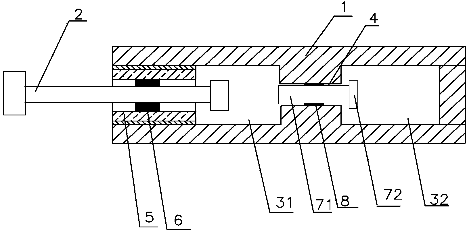
[0020] like figure 1 As shown, the damping device used in this embodiment to damp the vibration of the upper and lower rolls of the rolling mill includes a housing 1 with one end open, and two chambers are sequentially arranged in the housing, which are the first chamber 31 and the second chamber respectively. There are two chambers 32, and an air passage 4 is arranged between the first chamber and the second chamber.

[0021] The first chamber 31 communicates with the open end of the housing, and a support rod 2 is arranged in the first chamber along the center line of the first chamber, and the support rod extends to the outside of the housing. There is an airtight fit between the support rod and the first chamber.

[0022] A preferred airtight fit structure is as follows: a guide sealing ring 5 is sheathed on the outer periphery of the support rod, the guide seal ring and the inner wall of the first chamber are threaded, and the support rod and the inner wall of the first ...

Embodiment 2

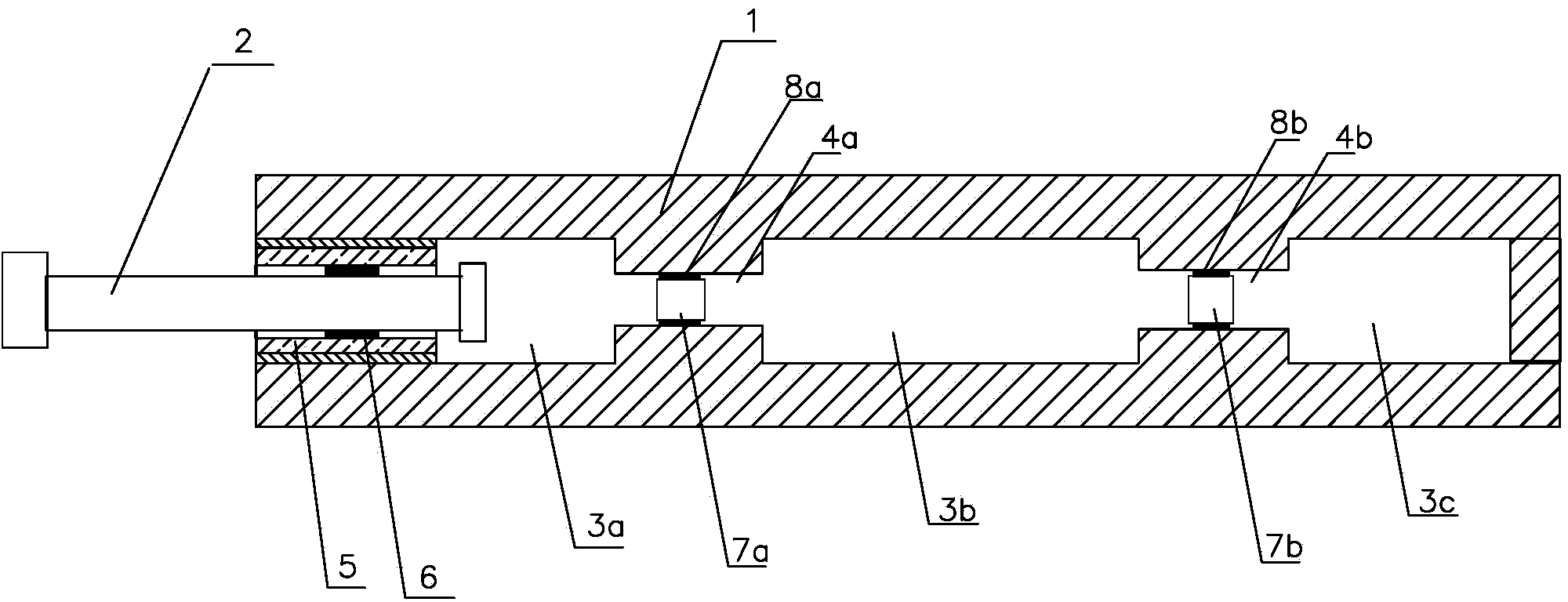
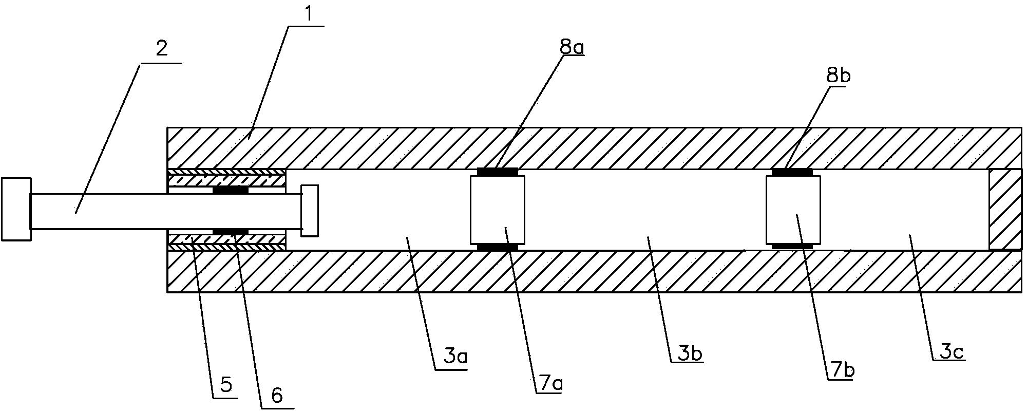
[0027] like figure 2 As shown, the damping device used in this embodiment to damp the vibration of the upper and lower rolls of the rolling mill includes a housing 1 with one end open, and three chambers are sequentially arranged in the housing, namely the first chamber 3a, the second chamber 3a, and the second chamber 3a. A chamber 3b and a third chamber 3c, a first air passage 4a is provided between the first chamber and the second chamber, a second chamber is provided between the second chamber and the third chamber Airway 4b.

[0028] The first chamber communicates with the opening end of the housing, and a support rod 2 is arranged in the first chamber along the direction of the center line of the first chamber, and the support rod extends to the outside of the housing. There is an airtight fit between the support rod and the first chamber.

[0029] A preferred airtight fit structure is as follows: a guide sealing ring 5 is sheathed on the outer periphery of the suppor...

Embodiment 3

[0035] The difference between this embodiment and the above-mentioned embodiment 2 is only that the diameter of each air channel is equal to the diameter of each chamber.

[0036] The greater the number of chambers provided in the present invention, the more obvious the buffering effect of the other chambers on the first chamber, and the smoother the damping force produced by the first chamber on the support rods, thus providing the upper and lower rolls Provides more stable support.


PUM


Abstract

The invention discloses a damping device for vibration attenuation of upper rollers and lower rollers of rolling mills. The damping device can reduce the repair load and provide stable supporting force for the rollers, and comprises a casing with one end opened. At least two cavities are arranged in the casing, air ducts are arranged between adjacent cavities, and a supporting rod in airtight fit with the first cavity is arranged in the first cavity. Sliding devices are arranged in the air ducts and are in airtight fit with the inner walls of the air ducts, and air is filled in each cavity. The cavity disposed behind the first cavity has a buffer effect and the damping force of the first cavity on the supporting rod changes gently so that the supporting rod provides stable supporting force for the upper rollers and the lower rollers, and the purpose of vibration attenuation of the upper rollers and the lower rollers can be achieved. Compared with the existing hydraulic cylinder, the damping device does not need piping and has no oil leakage phenomenon, thereby being little in the repair load.

Description

technical field [0001] The invention relates to a damping device used for damping the upper and lower rolls of a rolling mill. Background technique [0002] In the steel rolling production line, the rolling mill plays a very important role, but the vibration generated by the upper and lower rolls of the rolling mill during the opening and closing process will directly affect the quality of the rolled steel products. [0003] At present, the upper and lower rolls are mainly supported by hydraulic cylinders or damping devices to eliminate the vibration of the rolls. The hydraulic cylinders can provide stable support for the two rolls during the opening and closing process of the upper and lower rolls. However, the hydraulic cylinders also need to be piped, often Oil leakage occurs and the maintenance frequency is high, resulting in low production efficiency of rolled steel products. And the concrete structure of existing damping device mainly is: a passage runs through in the...

Claims


Application Information

Patent Timeline
Patent Type & Authority Applications(China)
IPC IPC(8): F16F9/02F16F9/32F16F9/36
CPCF16F9/0218F16F9/0227F16F9/0281
Inventor 江伟岳峰刘庆祖
Owner HUATIAN ENG & TECH CORP MCC
Learn More