Hydraulic tensioner

A tensioner and hydraulic technology, applied to belts/chains/gears, mechanical equipment, transmissions, etc., can solve problems such as increased engine energy consumption, chain vibration, and impact on vehicle NVH performance, achieving easy layout and compact structure Effect

Inactive Publication Date: 2018-06-29
SCHAEFFLER TECH AG & CO KG
View PDF0 Cites 3 Cited by
  • Summary
  • Abstract
  • Description
  • Claims
  • Application Information

AI Technical Summary

Problems solved by technology

[0004] However, in the prior art, the pressure relief valve is only opened when the engine is running at high speed. Since the timing chain is running at high speed, when the pressure relief valve is opened, the force of the hydraulic tensioner on the timing chain changes instantaneously, causing the chain to break down. Severe vibration affects the NVH performance of the car
In addition, when the engine is running at a medium speed, the force of the hydraulic tensioner on the timing chain is relatively large, and a large force is required to drive the timing chain to run, resulting in increased energy consumption when the engine is running

Method used


Image

  • Hydraulic tensioner
  • Hydraulic tensioner
  • Hydraulic tensioner

Examples


Embodiment Construction

[0033] In order to make the above objects, features and advantages of the present invention more comprehensible, specific embodiments of the present invention will be described in detail below in conjunction with the accompanying drawings.

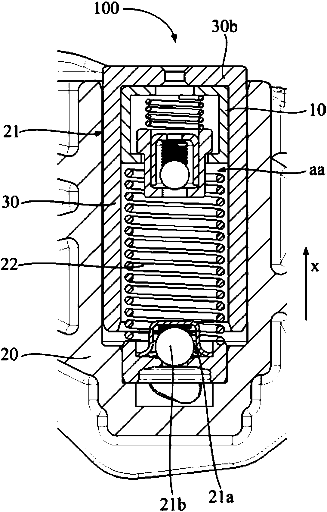
[0034] refer to figure 1 , a hydraulic tensioner 100, comprising a tensioner housing 20 and a plunger 30. Wherein, the tensioner housing 20 has a damping hole 21, and the bottom of the damping hole 21 is provided with a liquid inlet hole 21a, and the pressure medium (such as hydraulic oil, etc.) can enter the damping hole 21 through the liquid inlet hole 21a; The plug 30 is arranged in the damping hole 21, the inside of the plunger 30 forms a pressure chamber aa, the pressure chamber aa runs through the bottom of the plunger 30 to communicate with the damping hole 21, and the top of the plunger 30 protrudes to the damping hole 21 In addition, it is used to offset the conveyor chain or conveyor belt of the engine.

[0035] The first coil ...


PUM


Abstract

A hydraulic tensioner comprises a tensioner shell, a plunger and a pressure release valve, wherein the tensioner shell is provided with a damping hole; the plunger is arranged in the damping hole; a pressure cavity is formed in the plunger; the plunger is suitable for moving and extending out along an axial direction of the damping hole to press a conveying chain or a conveying belt; the pressurerelease valve is arranged in the pressure cavity, and can be open to communicate the pressure cavity with the outside; the pressure release valve at least comprises two stages of pressure release mechanisms; and the pressure release mechanisms are suitable for being started under different pressures so as to adjust the tension of the plunger. By arrangement of the two stages of pressure release mechanisms, when the rotating speed of an engine is increased, a pressure medium in the pressure cavity can flow out to the outside gradually, thus, pressure intensity change in the pressure cavity cantend to be gentle, similarly, change of acting force applied to the conveying chain or the conveying belt also tends to be gentle, violent vibration of the conveying chain or the conveying belt cannotbe caused, and large influences to NVH performance of an automobile cannot be caused.

Description

technical field [0001] The invention relates to the technical field of automobile engines, in particular to a hydraulic tensioner. Background technique [0002] The engine timing system usually uses a timing chain drive. In the prior art, a hydraulic tensioner is usually arranged on the loose side of the timing chain. The hydraulic tensioner can exert force on the timing chain to maintain a certain tension, thereby suppressing the vibration generated by the chain transmission, reducing the impact on related parts during the transmission process, reducing transmission noise, and improving driving comfort. [0003] The force of the hydraulic tensioner on the timing chain generally increases with the increase of the engine speed. When the engine is running at high speed, in order to prevent the hydraulic tensioner from exerting excessive force on the timing chain and damaging the timing chain, a pressure relief valve is usually installed in the hydraulic tensioner. , When th...

Claims


Application Information

Patent Timeline
Patent Type & Authority Applications(China)
IPC IPC(8): F16H7/08
CPCF16H7/08
Inventor 李鹏飞薛新程王飞
Owner SCHAEFFLER TECH AG & CO KG
Why Eureka
Try Eureka