
Vibration energy collection device based on piezoelectric stack and electromagnetic induction

A vibration energy harvesting, electromagnetic induction technology, applied in piezoelectric effect/electrostrictive or magnetostrictive motors, electromechanical devices, generators/motors, etc., can solve the problem of low output power, complex structure, narrow working bandwidth, etc problem, to achieve high power generation efficiency, improve work efficiency, and improve the effect of output power

Active Publication Date: 2021-03-19
SHANGHAI UNIV
View PDF11 Cites 0 Cited by
  • Summary
  • Abstract
  • Description
  • Claims
  • Application Information

AI Technical Summary

Problems solved by technology

At present, scholars at home and abroad have developed a large number of vibration energy harvesters, but there are generally problems of narrow working bandwidth, low output power (voltage) or complex structure.

Method used


Image

  • Vibration energy collection device based on piezoelectric stack and electromagnetic induction
  • Vibration energy collection device based on piezoelectric stack and electromagnetic induction
  • Vibration energy collection device based on piezoelectric stack and electromagnetic induction

Examples


Embodiment Construction

[0019] The following will clearly and completely describe the technical solutions in the embodiments of the present invention with reference to the accompanying drawings in the embodiments of the present invention. Obviously, the described embodiments are only some, not all, embodiments of the present invention. Based on the embodiments of the present invention, all other embodiments obtained by persons of ordinary skill in the art without making creative efforts belong to the protection scope of the present invention.

[0020] The purpose of the present invention is to provide a vibration energy harvesting device based on piezoelectric stack and electromagnetic induction, so as to solve the problems existing in the prior art.

[0021] In order to make the above objects, features and advantages of the present invention more comprehensible, the present invention will be further described in detail below in conjunction with the accompanying drawings and specific embodiments.

[...


PUM


Abstract

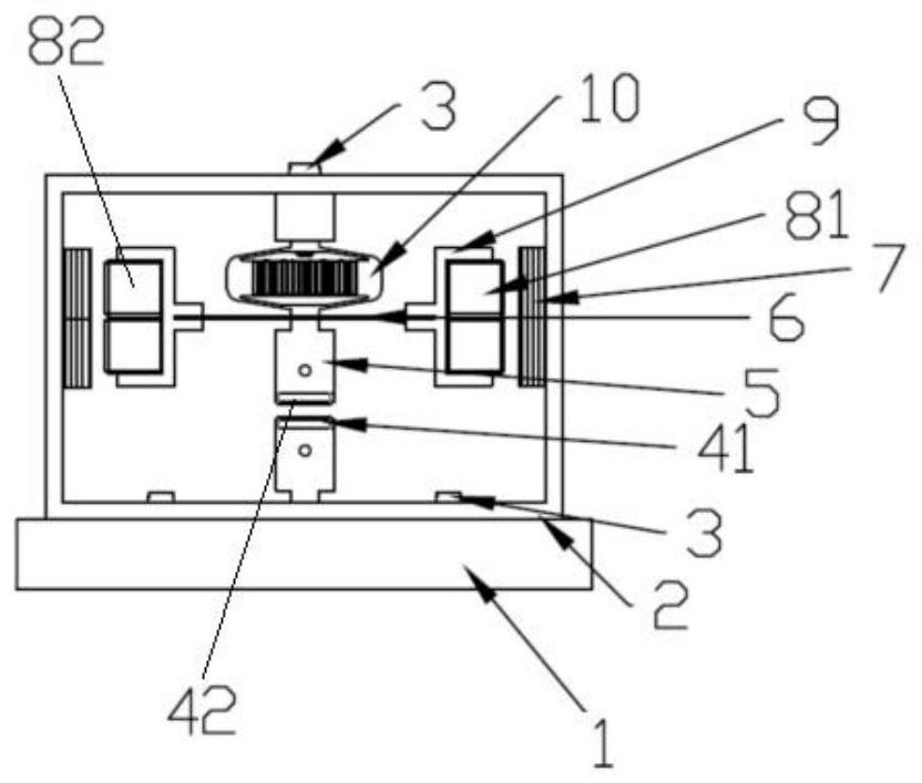
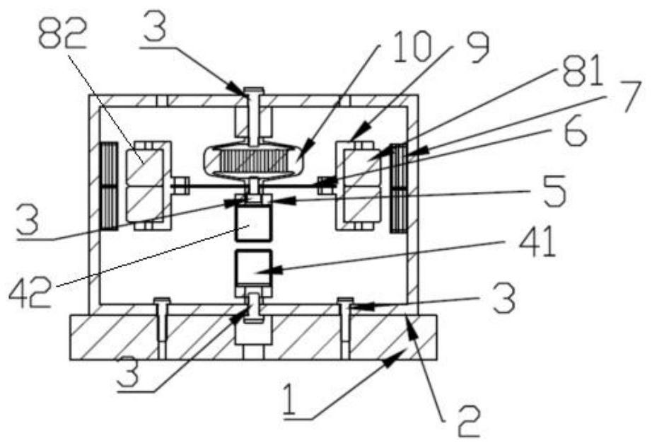
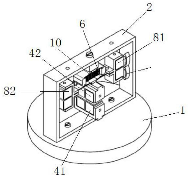
The invention discloses a vibration energy collection device based on piezoelectric stack and electromagnetic induction, and the device sequentially comprises a device pedestal, a device frame, an amplitude amplification mechanism and an energy collection mechanism from the bottom to the top, and the amplitude amplification mechanism comprises a piezoelectric device, a first magnet array and a second magnet array. The energy collection mechanism comprises a cantilever beam, a third magnet array, a fourth magnet array and an electric induction coil, and compared with other energy collection devices, the device has the advantages that vibration is more fully utilized, and more output energy can be obtained.

Description

technical field [0001] The invention relates to the technical field of energy collection, in particular to a vibration energy collection device based on piezoelectric stacks and electromagnetic induction. Background technique [0002] With the rapid development of microelectromechanical technology, microelectronic technology, embedded technology and wireless communication technology, a large number of low-power electronic devices appear, but these devices rely heavily on the supply of external power. At present, the commonly used energy supply method is to supply energy to chemical batteries, but the life of chemical batteries is limited, which seriously restricts the performance of the device itself. Given the low power consumption of the device, extracting energy from the device's surrounding environment to power the device is an ideal alternative. The energy contained in the environment mainly includes solar energy, wind energy, tidal energy, and mechanical vibration ene...

Claims


Application Information

Patent Timeline
Patent Type & Authority Applications(China)
IPC IPC(8): H02N2/18H02K35/02
CPCH02N2/186H02N2/183H02K35/02
Inventor 张泉刘子玉李忠杰彭艳罗均谢少荣蒲华燕
Owner SHANGHAI UNIV
Learn More