
Voltage dip source positioning method based on disturbance power direction

A technology of voltage sag source and location method, which is applied in the direction of fault location, electrical digital data processing, special data processing application, etc., and can solve the problem of low accuracy of voltage sag location

Inactive Publication Date: 2015-01-07
CHINA UNIV OF MINING & TECH +2
View PDF7 Cites 18 Cited by
  • Summary
  • Abstract
  • Description
  • Claims
  • Application Information

AI Technical Summary

Problems solved by technology

These positioning methods have a relatively high accuracy rate for voltage sags caused by symmetrical faults, but low accuracy for voltage sags caused by asymmetrical faults, and are only suitable for single-circuit radial grids.

Method used


Image

  • Voltage dip source positioning method based on disturbance power direction
  • Voltage dip source positioning method based on disturbance power direction
  • Voltage dip source positioning method based on disturbance power direction

Examples


Embodiment 1

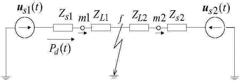
[0030] Embodiment 1: The present invention is based on the superposition principle of linear circuits, and under the action of disturbance voltage in the grid fault process, the direction of the disturbance active power flow is used to accurately locate the voltage sag source; when the disturbance active power is positive, the disturbance source is under monitoring upstream of the monitoring point; when the disturbance active power is negative, the disturbance source is downstream of the monitoring point;

[0031] Specific steps are as follows:

[0032] Step a. Set up a phase-locked loop. When the power grid is operating normally, that is, before the voltage sag occurs, the three-phase voltage and current are respectively sampled at N points synchronously at each fundamental wave cycle at the monitoring point: u ami (n), u bmi (n), u cmi (n) and i ami (n), i bmi (n), i cmi (n); for the neutral point effectively grounded power grid, calculate the root mean square value of ...


PUM


Abstract

The invention provides a voltage dip source positioning method based on the disturbance power direction and belongs to automatic monitoring methods for power grid voltage dip source positioning. The method is characterized in that under the effect that a disturbance voltage in a power grid fault process is obtained according to the superposition principle of linear circuits, the direction of an active disturbance power flow is used for accurately positioning a voltage dip source; when active disturbance power is positive, a disturbance source is located at the upstream portion of a monitoring point; when the active disturbance power is negative, the disturbance source is located at the downstream portion of the monitoring point; an algorithm of the corresponding disturbance power is given. The voltage dip source positioning method can be used for certainly positioning voltage dips caused by various power grid faults, is suitable for radiation type or ring type or single-circuit type or two-circuit type or single-power-supply type or multi-power-supply type grid structure power grids, and is also suitable for voltage dip source positioning caused by capacitor switching, transformer switching and large motor starting disturbance; according to the voltage dip source positioning method, the voltage and current of the monitoring point need to be sampled synchronously.

Description

technical field [0001] The invention relates to an automatic monitoring method for locating a power grid voltage sag source, in particular to a method for locating a voltage sag source based on a disturbance power direction. Background technique [0002] Voltage sag refers to a phenomenon in which the root mean square value of the supply voltage suddenly drops to 90% to 10% of the rated voltage amplitude in a short period of time, and its typical duration is 10ms to 1min. Some highly automated equipment is easily affected by voltage sags, and several cycles of voltage sags will cause huge economic losses to industrial production. According to foreign surveys, voltage sags have become the main cause of complaints in power quality problems, and even account for 80% of the proportion of complaints. However, electric energy is a special product that is provided by the power sector to power users and whose quality is jointly guaranteed by both the power supplier and the power us...

Claims


Application Information

Patent Timeline
IPC IPC(8): G01R31/08G06F19/00
Inventor 唐轶陈奎文雷黄巧娜韩冬方永丽刘昊
Owner CHINA UNIV OF MINING & TECH
Learn More