Conveyor belt

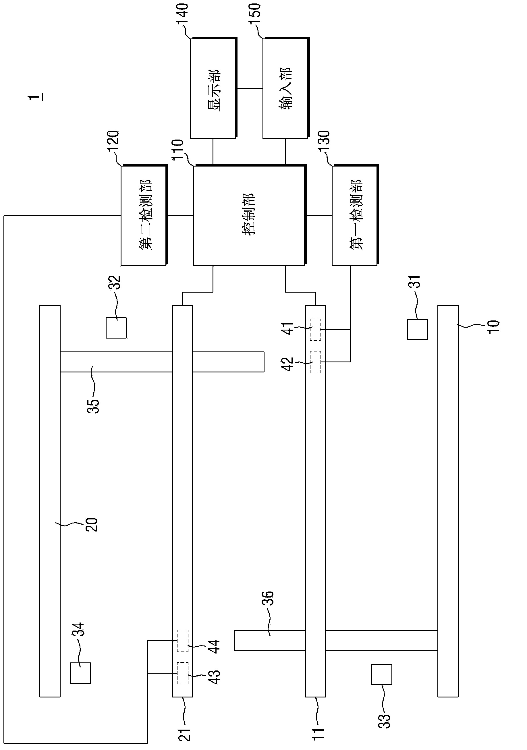
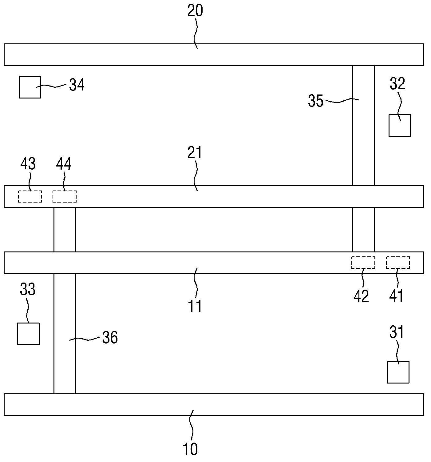
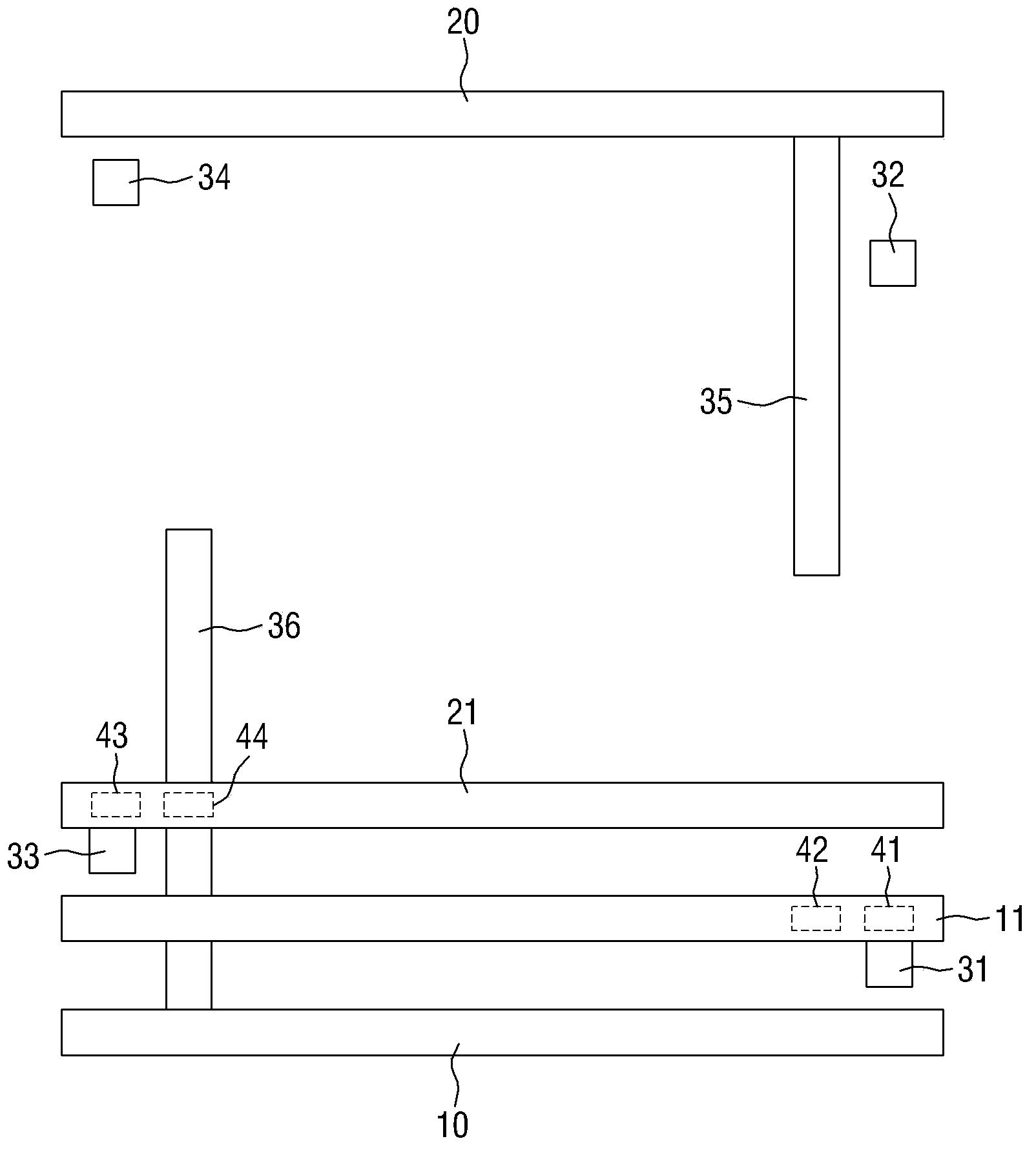
A conveyor belt and sensor technology, applied in the field of conveyor belts, can solve problems such as errors, two rails colliding with each other, and failure to detect the position of two movable rails, so as to improve efficiency and productivity, and ensure the continuity of operations.

Inactive Publication Date: 2015-01-14
HANWHA AEROSPACE CO LTD
View PDF6 Cites 0 Cited by
  • Summary
  • Abstract
  • Description
  • Claims
  • Application Information

AI Technical Summary

Problems solved by technology

[0005] However, when using a two-lane conveyor belt, there is no function to detect the positions of the two movable rails when the conveyor is initially started or restarted due to an error, and the operator needs to rearrange the two movable rails manually.
[0006] In addition, when restarting the conveyor belt, even if the function of moving the two movable rails to the initial position is included, because there is no function of detecting the positions of the two movable rails, it will be difficult to move the two movable rails to the initial position. In the process of moving to the original position, the two tracks collide with each other or the error occurs again during the movement to the starting position
[0007] In addition, usually the starting position of the two-lane conveyor belt is set at the center of the two movable rails, but in order to transfer large printed circuit boards, one lane of the two-lane is adjusted to a wide width, and the other lane is minimized. In the case of a single lane, it is more troublesome to move back to the two tracks at the starting position

Method used


Image

  • Conveyor belt
  • Conveyor belt
  • Conveyor belt

Examples


Embodiment Construction

[0045] Advantages and features and prior methods of the present invention will become apparent with reference to the accompanying drawings and embodiments to be described in detail. However, the present invention is not limited by the following embodiments and can be realized in various forms. The purpose of this embodiment is to better illustrate the present invention and provide help for those skilled in the art of the present invention to understand, and the present invention Limited only by the claims. In this specification, the same reference numerals refer to the same elements.

[0046] Although the terms "first, second" and the like are used to describe various elements, structures and / or parts, these elements, structures and / or parts are not limited by these terms. These terms are only used to distinguish one element, structure or section from other elements, structures or sections. Therefore, the following "first element, second structure or first part" may also be ...


PUM


Abstract

The invention provides a conveyor belt, which comprises a front fixed track, a rear fixed track parallel to the front fixed track, a front movable track between the front fixed track and the rear fixed track and capable of moving while parallel to the front fixed track, a rear movable track between the front movable track and the rear fixed track and capable of moving while parallel to the rear fixed track, a detection part used for detecting the position of the front movable track and the position of the rear movable track; a control part used for selecting the initial positions of the front movable track and the rear movable track based on the above detected positions of the front movable track and the rear movable track, and moving the above front movable track and the rear movable track to the above initial positions.

Description

technical field [0001] The invention relates to a conveyor belt, in particular to a two-lane conveyor belt with adjustable lane width. Background technique [0002] Generally speaking, a component mounting device is a device that mounts various electronic products on a printed circuit board, and the printed circuit board is transferred to the work zone (work zone) in the component mounting device through a conveyor belt device, and in the work area, various The components are mounted in their respective positions on the transferred printed circuit board. [0003] Recently, the conveyor belt has been developed as follows: In order to improve productivity, two printed circuit boards are sent into the work area at the same time, and the two-lane method is used to send out the components mounted on the two printed circuit boards at the same time. Lane width, thus widely used with various sizes of printed circuit boards. [0004] A conveyor belt that can adjust the width of a d...

Claims


Application Information

Patent Timeline
Patent Type & Authority Applications(China)
IPC IPC(8): B65G21/22B65G15/60
CPCB65G15/60B65G21/22H05K13/0061H05K13/086
Inventor 徐荣硕朱容兑
Owner HANWHA AEROSPACE CO LTD
Why Eureka
Try Eureka