Apparatus, system and method for projecting images onto predefined portions of objects

An object and image technology, applied in the equipment field, can solve problems such as image deformation

Active Publication Date: 2015-01-14
CHRISTIE SA
View PDF16 Cites 11 Cited by
  • Summary
  • Abstract
  • Description
  • Claims
  • Application Information

AI Technical Summary

Problems solved by technology

[0003] In addition to the stated obstacles involved in making the projecting instrument follow moving objects, images projected onto those moving objects may still appear distorted
Relative movement between projector and target object presents difficulties in achieving accurate projection

Method used


Image

  • Apparatus, system and method for projecting images onto predefined portions of objects
  • Apparatus, system and method for projecting images onto predefined portions of objects
  • Apparatus, system and method for projecting images onto predefined portions of objects

Examples


Embodiment Construction

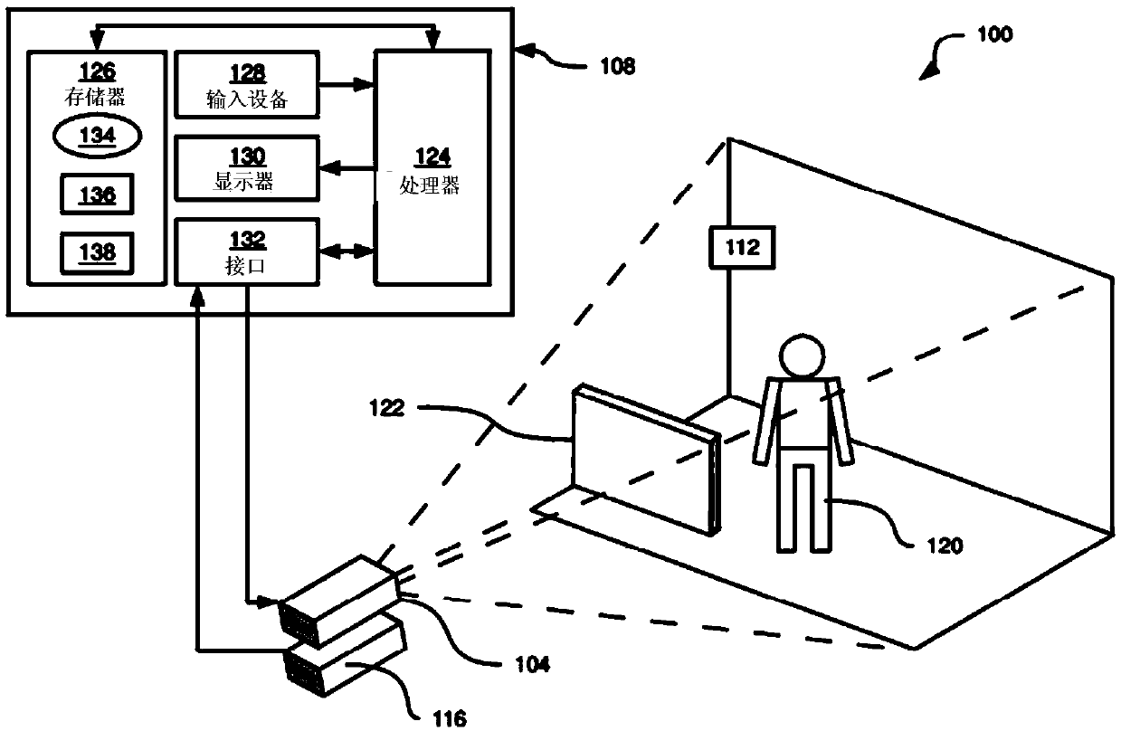
[0027] figure 1 A projection system 100 for projecting digital images is described. System 100 includes one or more projectors, such as projector 104 , arranged to project digital images received from computing device 108 (illustrated by dashed lines extending from projector 104 ) to projection area 112 . System 100 also includes one or more cameras, such as camera 116 , for capturing images of projection area 112 and sending the captured images to computing device 108 . Projector 104 and camera 116 are mounted in known, preferably fixed positions relative to each other, so that the position of any object relative to camera 116 can be used to determine the position of objects relative to projector 104 . Further, the field of view of the camera 116 includes the entire area of ​​the projection area 112 ; in other words, the camera 116 is configured to capture an image of an area at least as large as the area where the projector 104 projects light.

[0028] As will be described...


PUM


Abstract

Apparatus, systems and methods are provided for illuminating objects in a projection area. The system includes a computing device, a projector and a camera. The computing device stores a digital model of an object, and illumination data having lighting parameters and a reference to the digital model. The projector, or another light source, projects structured light onto the projection area, and the camera simultaneously captures an image of the projection area. The computing device receives the captured image, determines a position and orientation of the object by comparing the digital model to the captured image, and then generates a canvas image including a region matching the determined position and orientation of the object. The projector projects the canvas image onto the projection area. A predefined portion of the object corresponding to the reference in the illumination data is thereby illuminated according to the lighting parameters.

Description

technical field [0001] This specification relates generally to digital projection systems, and in particular to a method, system and apparatus for projecting digital images on a projection area, and for illuminating a projection area, particularly objects in the projection area A predefined portion of , to accommodate relative movement between the projection system and the object. Background technique [0002] Projection systems are typically used to project a fixed, predetermined image onto a flat, static surface. When the surface being projected is not flat, careful calibration may be required to account for the shape of the surface. Projecting an image onto a moving object presents additional complications: it is tedious to move the projector to track the object's movement such as with a moving spotlight. When multiple moving objects are involved, multiple projectors are required, and each projector needs to move independently relative to the other projectors to track i...

Claims


Application Information

Patent Timeline
Patent Type & Authority Applications(China)
IPC IPC(8): H04N5/74H04N9/31
CPCH04N9/3179G01B11/002G06T7/0057H04N9/3185H04N9/3194H04N5/74
Inventor 约翰·维尔茨罗伊·安东尼保罗·萨尔维妮
Owner CHRISTIE SA
Why Eureka
Try Eureka