
Lifting antiskid transmission track

An anti-slip transmission and track technology, which is applied in conveyors, mechanical conveyors, transportation and packaging, etc., can solve problems such as difficulty in ensuring smooth transportation of parts, insufficient stability of adjustable transmission tracks, and easy slipping of transported parts. Achieve the effect of simple structure, convenient operation and easy manufacture

Inactive Publication Date: 2015-01-21
WUHU HUANQIU AUTO PARTS
View PDF3 Cites 0 Cited by
  • Summary
  • Abstract
  • Description
  • Claims
  • Application Information

AI Technical Summary

Problems solved by technology

[0006] In view of the insufficient stability of the existing adjustable transmission track, it is difficult to ensure that the parts can be transported smoothly, and the transported parts are easy to slip, and the transport efficiency is low

Method used


Image

  • Lifting antiskid transmission track
  • Lifting antiskid transmission track

Examples


Embodiment 1

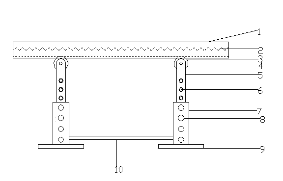
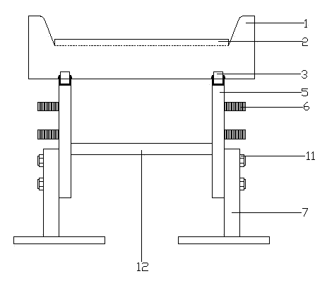
[0027] Such as figure 1 and figure 2 As shown, it includes a transmission plate 1, an anti-skid plate 2, a pulley 3, a first support plate 5, a second support plate 7, a base 9, a first connecting rod 10 and a second connecting rod 12, and the upper surface of the transmission plate 1 is Trapezoidal concave surface, anti-skid plates 2 are provided on both sides of the lower surface along the transmission direction; studs 6 arranged at equal intervals are provided on one side of the first support plate 5, and are connected with the pulley 3 through the bearing 4, and the top of the pulley 3 It is tangent to the lower surface of the anti-skid plate 2; there are N pulleys 3, N is an integer, and they are evenly distributed on the bottom of the anti-skid plate 2; the second support plate 7 is provided with studs on the first support plate 5 6 corresponding to N screw holes 8, and after the two are connected, they are fixed by nuts 11; the bottom surface of the second support pl...

Embodiment 2

[0031] Same as embodiment 1, the difference is that there are three screw holes 6 and three studs 5, which can ensure a more stable transmission plate.

Embodiment 3

[0033] The same as the embodiment 1, the difference is that the number of the screw holes 6 and the studs 5 are both five, and the height can be adjusted in a wider range.


PUM


Abstract

The invention discloses a lifting antiskid transmission track, and belongs to the field of automobile device production. The lifting antiskid transmission track comprises a transmission plate, antiskid plates, wheels, first supporting plates, second supporting plates, a base, a first connecting rod and a second connecting rod. The upper surface of the transmission plate is a trapezoid-shaped concave face. The zigzag antiskid plates are arranged on the two sides of the lower surface of the transmission plate in the transmission direction. Studs which are distributed at equal intervals are arranged on one side of each first supporting plate and are connected with the corresponding wheels through bearings. The top of each wheel is tangent to the lower surface of the corresponding antiskid plate. The number of the wheels is N, wherein N is an integer, and the wheels are evenly distributed at the bottoms of the antiskid plates. N screw holes corresponding to the studs on the first supporting plates are formed in the second supporting plates, and the screw holes and the studs are fixed through nuts after being connected. The bottom faces of the second supporting plates are fixed to the base. Limiting is conducted through bolts, and then the height of the transmission track is stably and reliably adjusted; the special structure is adopted for the transmission track, transported pieces can not slip from the two sides and are not prone to sliding along the antiskid plates, and therefore the transportation efficiency is improved.

Description

technical field [0001] The invention belongs to the field of automobile equipment production, and in particular relates to a lifting anti-slip transmission track. Background technique [0002] With the rapid development of my country's economy, the area of ​​various construction plants is gradually expanding, and many equipment manufacturing needs to transport various parts to designated processing points for processing. It needs to be done at a specific point, which brings the problem of difficult delivery of auto parts. Existing factories often use various transmission tracks to realize the transportation of auto parts, so as to achieve the purpose of transporting the transported parts from one place to another. [0003] The existing transmission track is basically fixed at a designated place and cannot be adjusted itself. However, due to the different production points of auto parts, it is often necessary to realize the transportation of the transported parts at different...

Claims


Application Information

Patent Timeline
Patent Type & Authority Applications(China)
IPC IPC(8): B65G35/00
Inventor 张天松胡仁农
Owner WUHU HUANQIU AUTO PARTS
Learn More