
False twister spindle and false twister
A false twister and spindle technology, applied in textiles and papermaking, can solve the problems of time-consuming and laborious assembly, complex structure of false twister spindle, etc., and achieve the effect of simple design
- Summary
- Abstract
- Description
- Claims
- Application Information
AI Technical Summary
Problems solved by technology
Method used
Image

Examples
Embodiment Construction
[0023] In order to make the above objects, features and advantages of the present invention more comprehensible, specific embodiments of the present invention will be described in detail below in conjunction with the accompanying drawings.
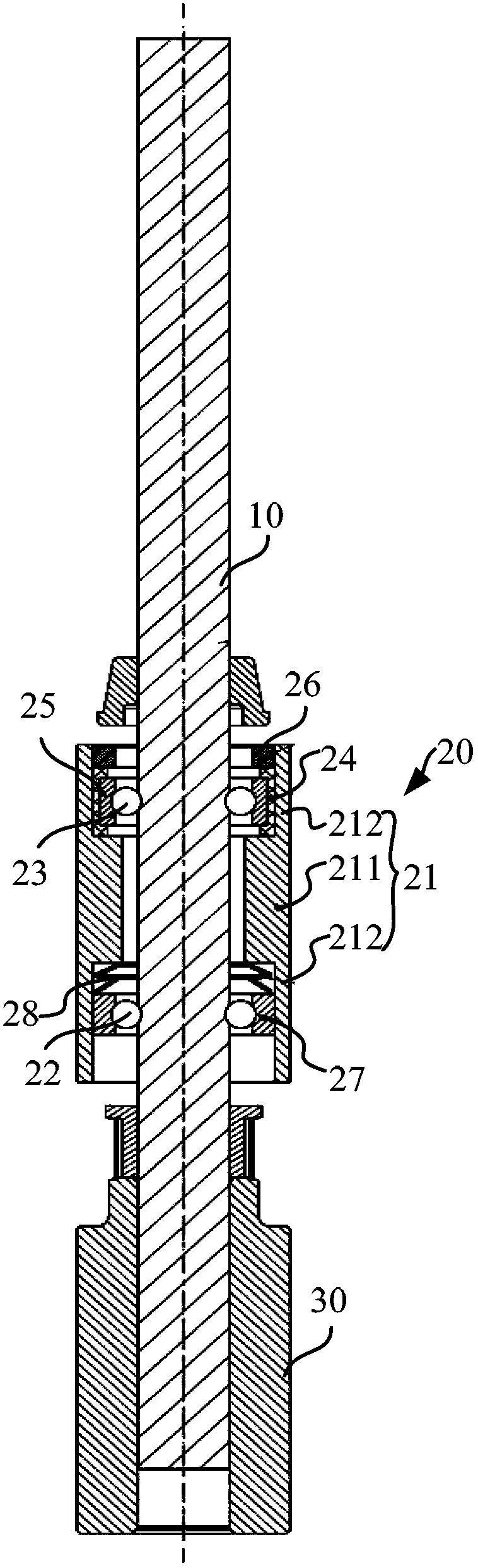
[0024] refer to figure 2 The false twister spindle includes a mandrel 10 , a bearing 20 surrounding the mandrel 10 , and a transmission member 30 located on the mandrel 10 and spaced apart from the bearing 20 along the axial direction of the mandrel 10 .
[0025] The bearing 20 includes a bearing outer ring 21, a first group of rolling elements 22 and a second group of rolling elements 23 located between the bearing outer ring 21 and the mandrel 10 and spaced from each other along the axial direction of the mandrel 10, the first group The rolling elements 22 are close to the transmission member 30 , and the second set of rolling elements are away from the transmission member 30 . The first set of rolling elements 22 and the second set of...
PUM
 Abstract
Description
Claims
Application Information