Eureka AIR delivers breakthrough ideas for toughest innovation challenges, trusted by R&D personnel around the world.

Transition device of hydraulic valve stand

A hydraulic valve, hydraulic technology, applied in the direction of fluid pressure actuation device, fluid pressure actuation system test, mechanical equipment, etc., can solve the problems of wasteful production cost, high market price, storage, placement, and inconvenient use.

Active Publication Date: 2015-01-21
LAIWU IRON & STEEL GRP
View PDF6 Cites 2 Cited by
  • Summary
  • Abstract
  • Description
  • Claims
  • Application Information

AI Technical Summary

Problems solved by technology

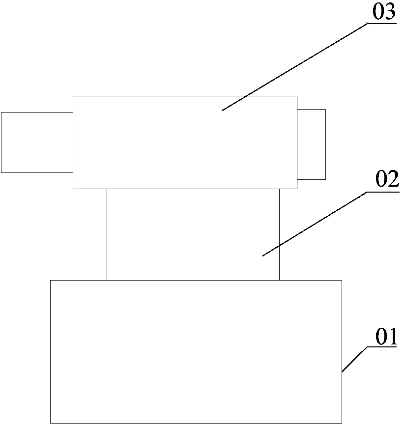
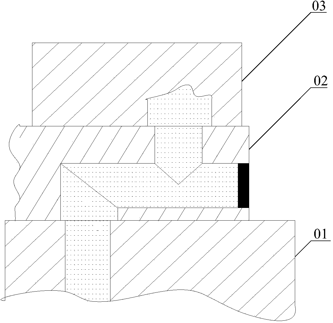
[0004] Affected by factors such as high-pressure oil, the transition valve block 02 is made of better materials, and the market price is relatively high, and it is also inconvenient to store, install, and use, which greatly wastes production costs

Method used


Image

  • Transition device of hydraulic valve stand
  • Transition device of hydraulic valve stand
  • Transition device of hydraulic valve stand

Examples


Embodiment Construction

[0032] The core of the present invention is to provide a transition device for a hydraulic valve platform, so as to reduce the cost of the transition device and further reduce the cost of hydraulic valve detection.

[0033] The following will clearly and completely describe the technical solutions in the embodiments of the present invention with reference to the accompanying drawings in the embodiments of the present invention. Obviously, the described embodiments are only some, not all, embodiments of the present invention. Based on the embodiments of the present invention, all other embodiments obtained by persons of ordinary skill in the art without making creative efforts belong to the protection scope of the present invention.

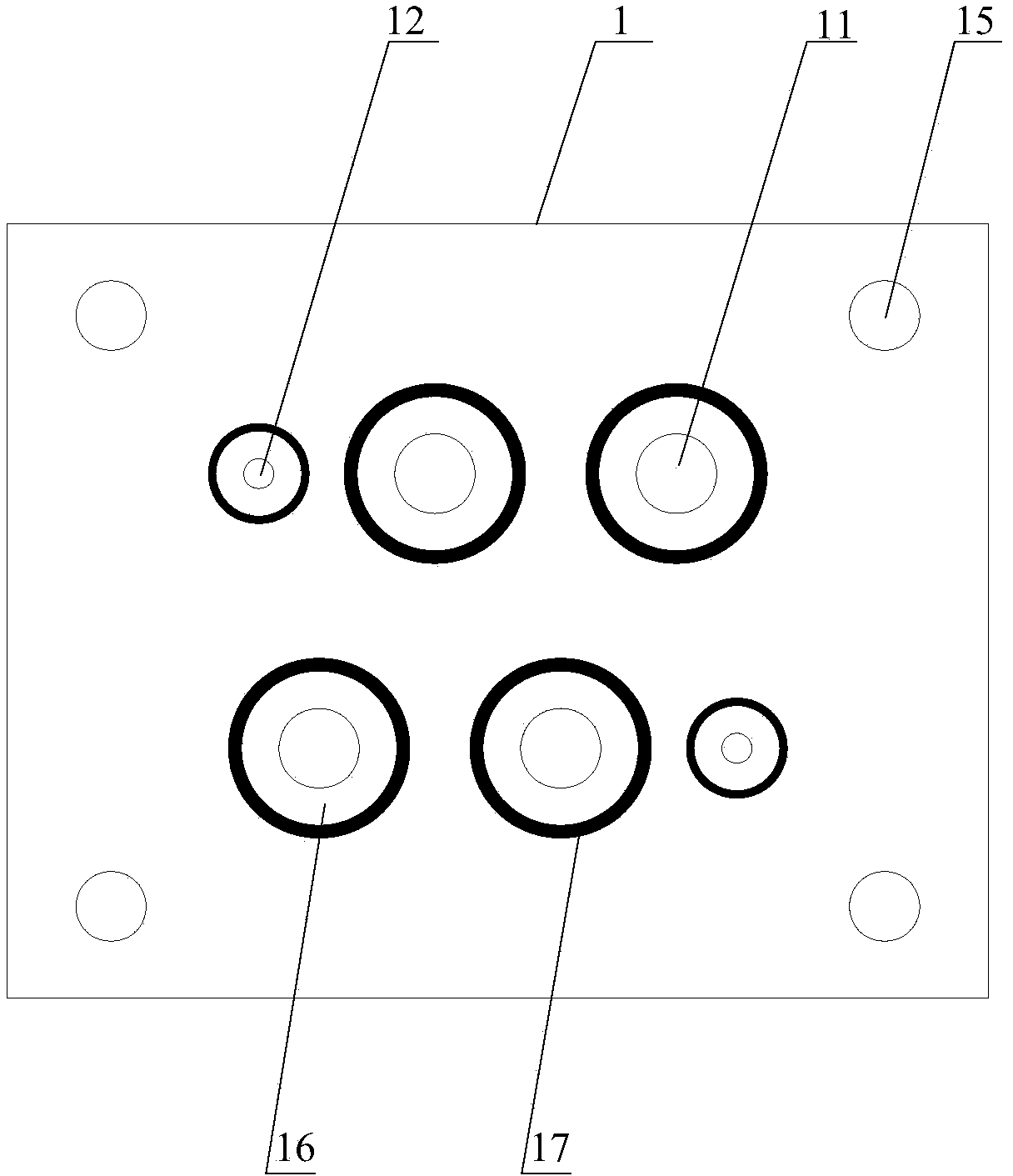
[0034] Please refer to Figure 3-Figure 10 As shown, among them, a transition device of a hydraulic valve table is used to connect the hydraulic valve table 3 and the hydraulic valve 4, which includes: a motherboard 1 for installation on the hydra...


PUM


Abstract

The invention discloses a transition device of a hydraulic valve stand. The transition device comprises a parent plate mounted on the hydraulic valve stand and a cover plate, the parent plate is provided with a first through hole communicated with an oil hole in the hydraulic valve stand, the cover plate detachably connected with the parent plate in an attached manner is provided with a second through hole capable of being communicated with an oil hole of a hydraulic valve, the surface, attached to the cover plate, of the parent plate is provided with an upper groove communicated with the first through hole, and the second through hole is communicated with the upper groove. The parent plate is mounted on the hydraulic valve stand, the first through hole of the parent plate is enabled to be communicated with the oil hole in the hydraulic valve stand, the cover plate is mounted on the parent plate, and the first through hole is communicated with the second through hole which is communicated with the oil hole of the hydraulic valve. The upper groove is formed in one end of the first through hole, so that relative range of the first through hole and the second through hole can be increased, the parent plate can fit the cover plate provided with the second through hole at different positions, and types of the hydraulic valves that the parent plate can adapt to are expanded. During use, only the cover plate rather than the parent plate needs to be replaced, and accordingly cost of the transition device is reduced.

Description

technical field [0001] The invention relates to the field of hydraulic valve detection, in particular to a transition device for a hydraulic valve table. Background technique [0002] There are many hydraulic valves such as private valves and proportional valves used in enterprise production lines. If the valve fails to operate or has other faults during use, it needs to be tested offline to determine whether it is worth repairing. [0003] At present, the test bench in the laboratory is a fixed and single-set valve bench. Because there are many types of hydraulic valves, the diameters of the bottom surface of the valve are different. During the test bench test, it is necessary to provide a valve that matches the test bench for each type of valve. Transition valve block for connection to test benches. like figure 1 and figure 2 As shown, specifically, the upper surface of the transition valve block 02 matches the oil hole on the bottom surface of the hydraulic valve 03,...

Claims


Application Information

Patent Timeline
IPC IPC(8): F15B19/00
CPCF15B19/00F15B19/005
Inventor 陈传盛邵宪伟葛本伍陈利李亮张谱刘争高伟朱迎春
Owner LAIWU IRON & STEEL GRP
Why Eureka
Eureka Blog
Learn More