Monitoring device and method

A monitoring device and monitored technology, applied in digital transmission systems, electrical components, transmission systems, etc., can solve problems such as abnormal handling, monitoring, and failure to realize automatic restart of abnormal systems

Inactive Publication Date: 2015-01-21
FOUNDER BROADBAND NETWORK SERVICE
View PDF6 Cites 2 Cited by
  • Summary
  • Abstract
  • Description
  • Claims
  • Application Information

AI Technical Summary

Problems solved by technology

In the case of mutual dependence between the monitored systems, when a system in the monitored system is abnormal, the monitoring system in the above scheme cannot notify other normal systems that rely on the abnormal system to work, so there is a dependency relationship with the abnormal system The normal system of the network cannot make corresponding actions, and in special cases such as network servers, it may have disastrous consequences, causing the entire network service to be paralyzed
[0005] In addition, the monitoring method in the above scheme in the prior art can detect that a certain system is abnormal, but after the abnormality occurs, the monitoring system can only send the abnormal information to the management personnel through SMS or email, and cannot realize the monitoring of the abnormal system itself. Operations such as automatic restart, it is impossible to control the abnormal system to return to normal operation, and the abnormal system can only be restored to normal operation through manual operations such as manual restart
However, the speed and efficiency of human operation are low, and the abnormal system cannot be restored to normal operation in the first time. In severe cases, it will directly lead to the collapse of the dependent system and bring about a chain reaction, which may cause the collapse of the entire network system.
[0006] Furthermore, the above-mentioned solutions in the prior art can only realize the monitoring of the monitored system through the monitoring system without considering whether the monitoring system itself is abnormal. Timely handling of exceptions will bring great stability to users, and may cause huge economic losses to users in severe cases

Method used


Image

  • Monitoring device and method
  • Monitoring device and method
  • Monitoring device and method

Examples


Embodiment 1

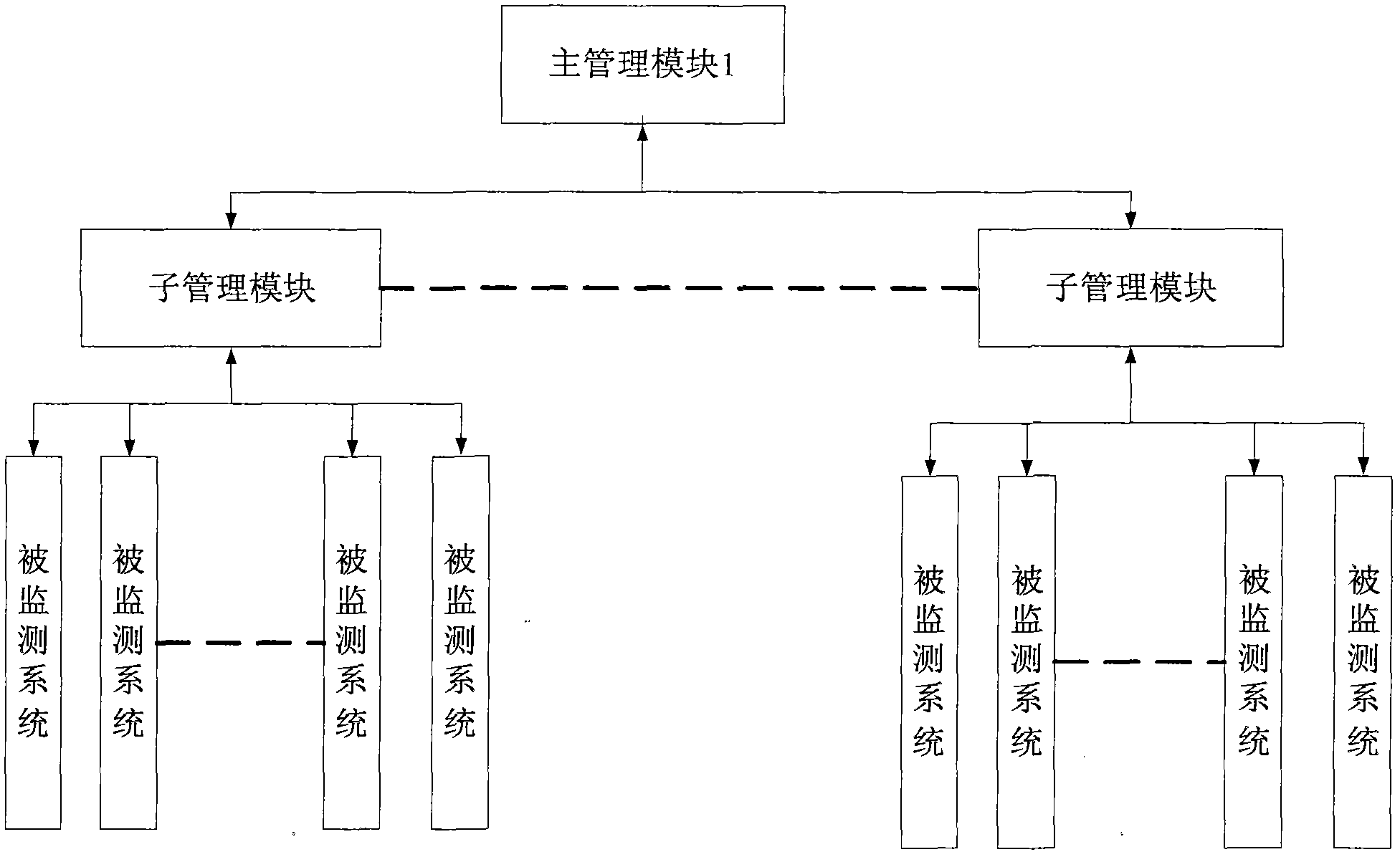
[0055] The monitoring device described in this embodiment, such as figure 2 As shown, it includes: a main management module 1 and several sub-management modules. Each of the sub-management modules is used to monitor a group of monitored systems; when the operating status of the monitored system changes, send the operating status change information of the monitored system to the main management module 1; The main management module 1 manages the dependency relationship between the monitored systems; after the main management module 1 receives the operation state change information of a certain monitored system sent by the sub-management module, it determines the dependent operation state change information according to the dependency relationship. The monitored system depends on the action mode of the system, and sends the action mode to the sub-management module for monitoring the dependent system, and the sub-management module controls the dependent system to perform correspo...

Embodiment 2

[0059] This embodiment makes the following improvements on the basis of Embodiment 1. In this embodiment, the change in the operating state of the monitored system includes from normal operation to abnormality. When the sub-management module detects that there is a monitored system from normal operation to an abnormality, it controls the abnormal monitored system to take corresponding actions, and sends the abnormality information of the monitored system to the main management module 1. After the main management module 1 receives the abnormality information of a certain monitored system sent by the sub-management module, it judges the action mode of the dependent system that depends on the abnormal monitored system according to the dependency relationship, and sends the action mode to the user For the sub-management module that monitors the dependent system, the sub-management module controls the dependent system to take corresponding actions.

[0060] In the monitoring device...

Embodiment 3

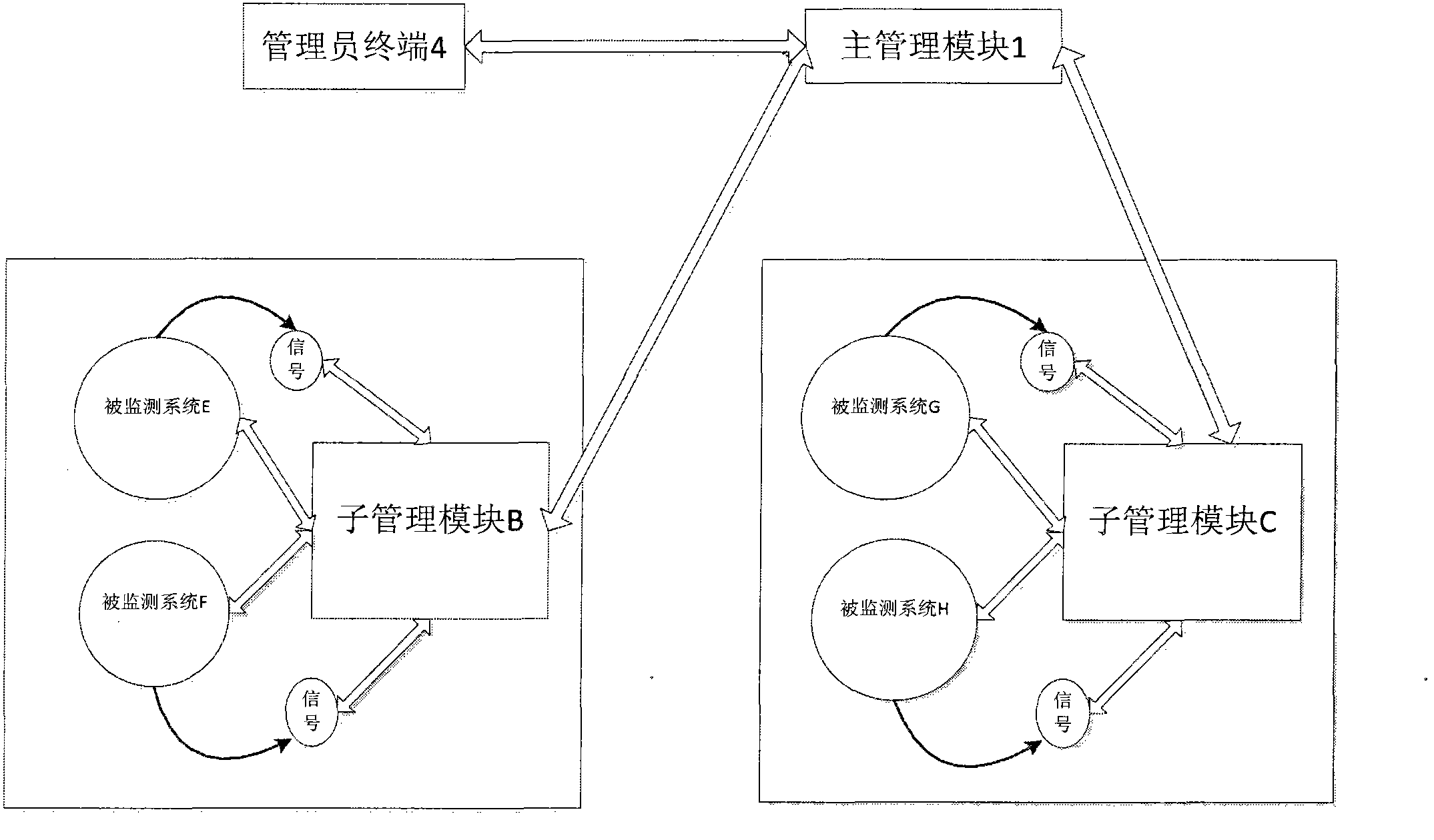
[0067] This embodiment makes the following improvements on the basis of Embodiment 1 or Embodiment 2. The function of the main management module 1 also includes abnormal monitoring of each of the sub-management modules. When a certain sub-management module occurs When an exception occurs, the main management module 1 sends an abnormal notification to the administrator terminal 4; and the main management module 1 obtains all monitoring information of all dependent systems according to the dependencies of all monitored systems monitored by the abnormal sub-management module. The action mode of the sub-management module, and send the action mode to the corresponding sub-management module.

[0068] by image 3 The block diagram shown is an example, the main management module 1 can also monitor the sub-management module B and the sub-management module C, if the sub-management module B is abnormal, the main management module 1 will send an abnormal notification to the administrator t...


PUM


Abstract

The invention relates to a monitoring device and a method. The device comprises a main management module, multiple sub management modules and a manager terminal. When one monitored system has abnormity, the corresponding sub management system corresponding to the abnormal monitored system takes control and processing actions without any manual auxiliary operation. The main management module makes determination, employs corresponding motion modes for the dependent monitored system and notifies the dependent monitored system to take corresponding motions through the corresponding sub management module. After the abnormal system recovers, the whole system functions recover through steps above gradually. A user can communicate with the main management module through a management interface and can send a special instruction to the monitored system. Through the method and the device, a problem that the whole dependent system is abnormal or even collapses because of abnormity of one system can be effectively settled.

Description

technical field [0001] The invention relates to the technical field of server clusters, in particular to a monitoring device and method. Background technique [0002] In the network environment, most of the network servers are composed of server clusters, and each server runs different systems, and the systems may also depend on each other. Due to the complexity of the network environment, the possibility of abnormalities in the system is greatly increased. If there is an abnormality in one system in the server cluster, it may have a major impact on the entire server cluster, causing the loss of normal functions of the entire server cluster, thereby directly affecting the use of users. huge influence. In order to solve such problems, it is necessary to monitor each important system in the server cluster in real time. Once an abnormality is found in a system, it is necessary to notify the normal system that depends on its operation and restart the abnormal system, so as to m...

Claims


Application Information

Patent Timeline
IPC IPC(8): H04L12/26H04L12/24
Inventor 朱庆昌李晓阳聂志吴雨果
Owner FOUNDER BROADBAND NETWORK SERVICE
Why Eureka
Try Eureka