a locker

A storage cabinet and storage box technology, applied in the field of storage cabinets, can solve the problems of large space volume and low space utilization rate, and achieve the effects of high space utilization rate, reasonable structure design, and compact and reasonable layout.

Active Publication Date: 2017-01-18
HUAQIANG FANGTE WUHU CULTURE TECH CO LTD
View PDF6 Cites 0 Cited by
  • Summary
  • Abstract
  • Description
  • Claims
  • Application Information

AI Technical Summary

Problems solved by technology

[0004] A locker, comprising a cabinet body, square grooves are provided on the front part of the right side of the cabinet body, and on the rear part of the right side, and a feed plate and a discharge plate are installed in the square grooves. The feed plate is located directly above the discharge plate, and there are chutes arranged above the front end surface and the rear end surface inside the cabinet, and the chute is arranged in parallel along the length direction of the cabinet body, and is located above the front end surface inside the cabinet body The lower part of the chute constitutes the front storage area, and the lower part of the chute located above the rear end surface inside the cabinet constitutes the rear storage area. The front storage area and the rear storage area are symmetrical about the middle part of the cabinet body. area, can make full use of the space in the cabinet, compared with the traditional single-side locker, the storage capacity can be doubled, the space utilization rate is high, the layout is compact and reasonable, and it solves the problem of placing multiple single-side lockers. The problem of large space volume and low space utilization rate of traditional lockers, so that the storage capacity can be doubled in areas with limited space, providing convenience for people's normal storage of goods

Method used


Image

  • a locker
  • a locker
  • a locker

Examples


Embodiment Construction

[0022] In order to make it easy to understand the technical means, creative features, achieved goals and effects of the present invention, the present invention is further described below.

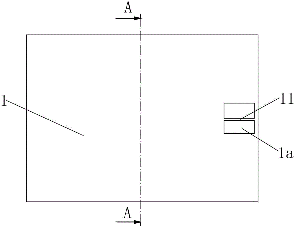
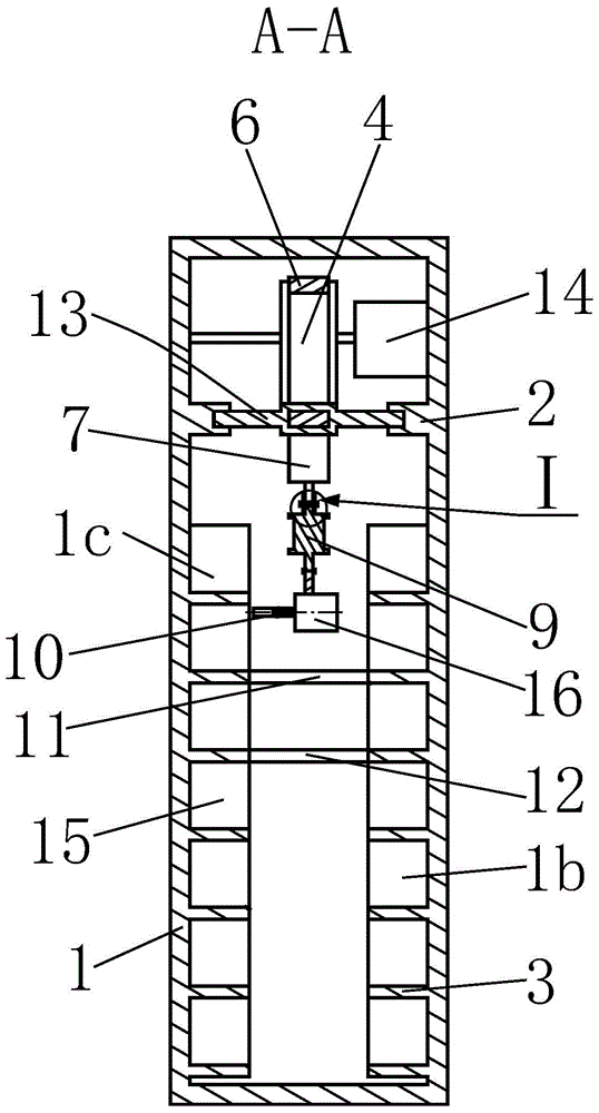
[0023] like Figure 1 to Figure 7 As shown, a storage cabinet includes a cabinet body 1, a square groove 1a is opened on the front part of the right side and the rear part of the right side of the cabinet body 1, and a feeding board is installed in the square groove 1a 11 and the discharge plate 12. The feed plate 11 is located directly above the discharge plate 12. The cabinet body 1 is provided with a chute 2 above the front end surface and above the rear end surface. The chute 2 runs along the cabinet. The length direction of the cabinet 1 is arranged in parallel, the front storage area 1b is formed under the chute 2 located above the inner front surface of the cabinet 1, and the rear storage area 1c is formed below the chute 2 located above the rear end surface of the cabinet 1. The f...


PUM


Abstract

The invention relates to a storage cabinet which comprises a cabinet body, wherein the front part and rear part of the right side of the cabinet body are provided with square grooves, the square grooves are internally provided with feeding plates and discharging plates, the upper sides of the front end surface and rear end surface of the interior of the cabinet body are respectively provided with a sliding chute, a front storage region is formed below the sliding chute at the front end surface of the interior of the cabinet body, and a rear storage region is formed below the sliding chute at the rear end surface of the interior of the cabinet body; a motor I is arranged above the sliding chute at the rear end surface of the cabinet body and is connected with a driving wheel; the left side of the driving wheel is provided with a driven wheel; a belt annularly sleeves between the driving wheel and the driven wheel; the lower side surface of the belt is provided with a motor II; the lower part of the motor II is connected with a coupling; the lower end of the coupling is provided with a cylinder; the lower end of the cylinder is connected with a lateral moving cylinder which is connected with a clamp. The storage cabinet is reasonable in structural design, convenient in operation and control, high in automatic degree, high space utilization rate and the like, and is capable of doubling the storage capacity and realizing dual-surface clamping and conveying by use of an automatic material taking mode.

Description

technical field [0001] The invention relates to a storage device for entertainment places, in particular to a storage cabinet. Background technique [0002] At present, in supermarkets, public bathrooms and playgrounds, lockers have become an indispensable item for people to shop for entertainment and leisure. Traditional lockers contain many lockable drawers, giving tourists one drawer as an item. of storage. However, this method is very inconvenient for tourists. When tourists store items, they must first find an empty drawer. After storing the items in and locking them, they must remember the specific location of the storage. After returning, they have to go to the original location. Pick. If people accidentally forget where they are stored, their belongings will be hard to reach. Therefore, such traditional lockers have very cumbersome problems in the use of storing and removing items; traditional lockers are all single-sided structures, that is, the items stored by t...

Claims


Application Information

Patent Timeline
Patent Type & Authority Patents(China)
IPC IPC(8): A47B53/00A47B96/00
CPCA47B53/00A47B96/00A47B2220/0091
Inventor 陈祖尧易伟林
Owner HUAQIANG FANGTE WUHU CULTURE TECH CO LTD
Why Eureka
Try Eureka