Driving device for microfluidic micro valve

A driving device and microfluidic technology, applied in valve devices, valve operation/release devices, valve details, etc., can solve the problems of hidden reliability, chip failure, easy leakage of micro-membrane pumps, etc., to improve reliability and facilitate the Parallel drive, the effect of reducing the chance of leakage

Active Publication Date: 2015-01-28
CHINESE ACAD OF INSPECTION & QUARANTINE
View PDF6 Cites 9 Cited by
  • Summary
  • Abstract
  • Description
  • Claims
  • Application Information

AI Technical Summary

Problems solved by technology

In order to use gas energy to drive the diaphragm, the system sets up a pneumatic interface for each micro-membrane pump. At the same time, in order to ensure that the chip can be easily disassembled, the pneumatic interface can only be temporarily sealed,

Method used


Image

  • Driving device for microfluidic micro valve
  • Driving device for microfluidic micro valve
  • Driving device for microfluidic micro valve

Examples


Example Embodiment

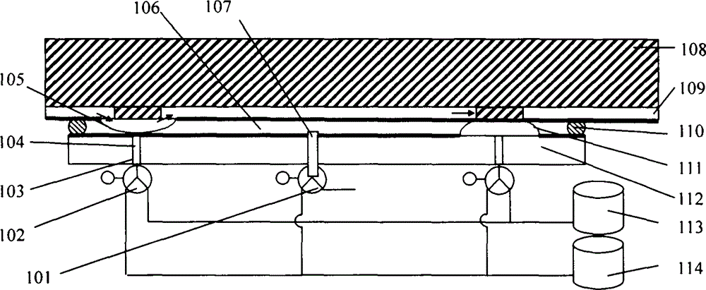
[0012] The solution of the present invention can drive the micro-membrane pump to achieve bidirectional fluid movement. In this example, a compressed gas bottle 213 is used to store positive pressure gas. The channel 203 is connected to the vacuum bottle 214 and the compressed gas cylinder 213 through three-way valves 202A, 202B, and 202C. 202A, 202B, and 202C control the positive and negative pressures in the channel 203. The compressed air 204 is used to transmit the positive pressure to the elastic sealing cap. The fluid driving process is divided into two steps: suction and discharge.
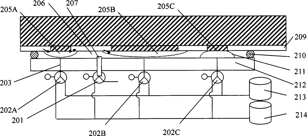
[0013] Such as Figure 2a Show the inhalation process. The three-way valve 201 connects the sealed space 206 to a negative pressure, and the chip is pressed on the chip tray 212. When the three-way valve 202A is switched to negative pressure and 202C is switched to positive pressure, the diaphragm 205A is opened and the diaphragm 205C is compressed. The corresponding fluid channel is conduct...


PUM


Abstract

The invention relates to a driving device for a diaphragm pneumatic micro valve as a basic functional unit of a micro diaphragm pump chip. The driving device consists of a positive pressure assembly, a negative pressure gas source, channels, positive pressure switching assemblies, a chip tray, sealing rings, elastic sealing caps and driving assemblies, wherein a negative pressure airtight space is arranged between the chip and the tray; the channels are arranged on the chip tray and correspond to diaphragms on the micro diaphragm pump chip in position; each elastic sealing cap is arranged at the top end of the corresponding channel; the channels are separated from the airtight space by the elastic sealing caps; when the elastic sealing caps are loosened, all diaphragms on the micro diaphragm pump chip are pulled open by negative pressure, and a fluid channel is conducted or liquid with certain volume is sucked into the fluid channel; when the positive pressure switching assemblies control to allow the positive pressure assembly to drive the sealing caps through the driving assemblies, and the sealing caps are stressed to deform and raise, the corresponding diaphragms on a microfluidic chip are pressed, and the fluid channel is blocked or the liquid with the certain volume is drained from the fluid channel. According to the driving device, an independent pneumatic connector is not needed for establishing for each micro diaphragm pump unit on the microfluidic chip, so the system failure caused by leakage is greatly reduced.

Description

technical field [0001] This patent relates to a microvalve driving device, in particular to a driving device for driving a membrane-moving microvalve, a basic functional unit on a micro-membrane pump chip. Background technique [0002] Existing laboratory analysis methods are often limited by factors such as complex pretreatment and detection processes, strict site requirements, etc., and are easily interfered by environmental and human factors. The microfluidic chip system is used to drive a small volume of fluid. It has good sealing properties, is easy to use, uses a small amount of samples, and is less disturbed by human factors. It has good applications in life science research, disease diagnosis, food safety, and environmental analysis. prospect. [0003] Plastic microfluidic chips have attracted extensive attention due to their advantages of one-time use and low cost. The invention patent (CN101282789) provides a variety of functional structures based on micro-membra...

Claims


Application Information

Patent Timeline
IPC IPC(8): F16K31/12
CPCF16K99/0055
Inventor 刘峰邹明强刘恩凯
Owner CHINESE ACAD OF INSPECTION & QUARANTINE
Why Eureka
Try Eureka