Microfluidic Microvalve and Driving Device

A driving device and microfluidic technology, applied in valve devices, components of pumping devices for elastic fluids, valve operation/release devices, etc., can solve reliability risks, easy leakage of micro-membrane pumps, chip failure, etc. problem, to achieve the effect of improving transmission efficiency, solving the failure of microvalve function, and convenient chip installation

Active Publication Date: 2018-01-09
CHINESE ACAD OF INSPECTION & QUARANTINE
View PDF7 Cites 0 Cited by
  • Summary
  • Abstract
  • Description
  • Claims
  • Application Information

AI Technical Summary

Problems solved by technology

In order to use gas energy to drive the diaphragm, the system sets up a pneumatic interface for each micro-membrane pump. At the same time, in order to ensure that the chip can be easily disassembled, the pneumatic interface can only be temporarily sealed, especially when the high-pressure gas pushes the micro-membrane pump, it is easy to leak
Since a large number of basic micro-membrane pump units need to be driven on the microfluidic chip, any unit leakage may cause the chip to fail, causing reliability risks

Method used


Image

  • Microfluidic Microvalve and Driving Device
  • Microfluidic Microvalve and Driving Device
  • Microfluidic Microvalve and Driving Device

Examples


Embodiment Construction

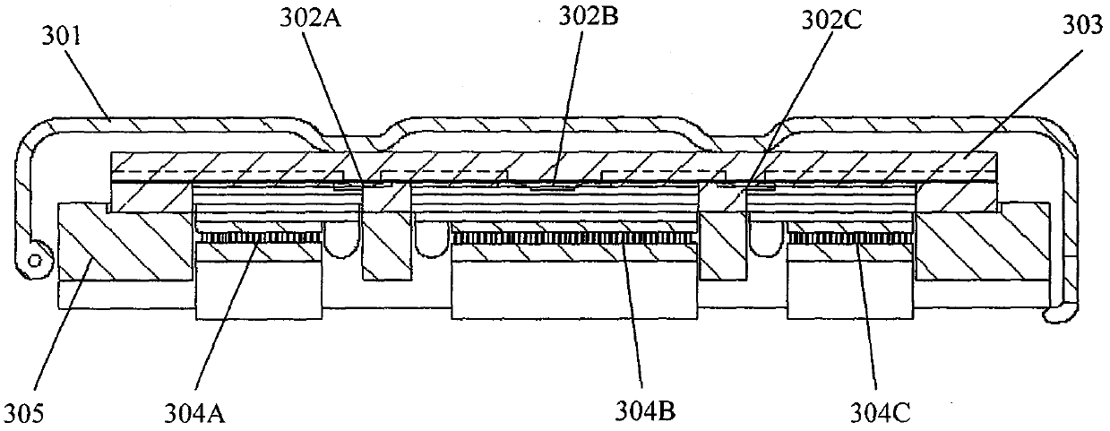
[0013] By adopting the solution embodiment of the present invention, the micro-membrane pump can be driven to realize bidirectional movement of fluid. Such as image 3 Three microfluidic microvalves 302A, 302B, and 302C provided by the present invention are connected in series on the chip 303 to form a two-way volume displacement pump. Among them, the microfluidic microvalve 302B in the middle is larger and constitutes a replacement cavity, and the microfluidic microvalves 302A and 302C are check valves. The chip 303 is fixed by the tray 305 and the clip 301, so that the heat exchange surfaces of the three microfluidic microvalves 302A, 302B, 302C on the chip 303 are in good contact with the heat control surfaces of the temperature control devices 304A, 304B, 304C on the tray 306. Each microvalve corresponds to a set of temperature control devices, and the closed-loop control of each microvalve on the chip 303 is realized through semiconductor refrigerators and temperature se...


PUM


Abstract

The invention relates to a micro valve structure as a basic functional unit of a micro diaphragm pump chip and a driving device. A microfluidic micro valve comprises a flow channel structural layer, a diaphragm layer, a driving structural layer, transmission fluid, a temperature sensitive material and a heat exchange surface. The driving device at least comprises a chip fixture, a temperature control device and a thermal control surface. The temperature sensitive material and the transmission fluid are closed in a chip by the micro valve structure; a driving force is generated by the solid-liquid state change of the temperature sensitive material; chip fluid is driven by temperature control for a thermal contact zone of the chip; various micro control devices on the chip can be evolved from the micro valve on the plastic microfluidic chip based on a micro diaphragm pump technology; the micro control devices form different combinations and are integrated according to the requirement, so the control over trace fluid on the chip can be realized. The scheme disclosed by the invention has the characteristics that the driving device is separated from the flow channel; the chip is easy for processing and low in cost; the connection of the chip and the driving device is simple and reliable; the driving device can be repeatedly used.

Description

technical field [0001] This patent relates to a microfluidic microvalve and a driving device, in particular to a basic functional unit microvalve and a driving device on a plastic microfilm pump chip. Background technique [0002] Existing laboratory analysis methods are often limited by factors such as complex pretreatment and detection processes, strict site requirements, etc., and are easily interfered by environmental and human factors. The microfluidic chip system is used to drive a small volume of fluid. It has good sealing properties, is easy to use, uses a small amount of samples, and is less disturbed by human factors. It has good applications in life science research, disease diagnosis, food safety, and environmental analysis. prospect. [0003] Plastic microfluidic chips have attracted extensive attention due to their advantages of one-time use and low cost. The invention patent (CN101282789) provides a variety of functional structures based on micro-membrane pu...

Claims


Application Information

Patent Timeline
Patent Type & Authority Patents(China)
IPC IPC(8): F16K31/70F04B43/02F04B53/10
CPCF16K99/0015F16K99/0036F16K2099/0094
Inventor 刘峰邹明强刘恩凯
Owner CHINESE ACAD OF INSPECTION & QUARANTINE
Why Eureka
Try Eureka