a transfer plate

A transfer printing plate and dot technology, applied in the display field, can solve the problems of uneven thickness of alignment film, abnormal orientation of liquid crystal molecules, uneven rubbing orientation, etc., and achieve the effects of reducing abnormal orientation, uniform rubbing orientation, and reducing average height

Inactive Publication Date: 2017-06-30
HEFEI BOE OPTOELECTRONICS TECH +1
View PDF7 Cites 0 Cited by
  • Summary
  • Abstract
  • Description
  • Claims
  • Application Information

AI Technical Summary

Problems solved by technology

[0006] The purpose of the present invention is to provide a transfer printing plate to solve the problem that the existing transfer printing plate structure causes the uneven thickness of the printed alignment film, which leads to the abnormal orientation of liquid crystal molecules caused by the uneven orientation of subsequent rubbing

Method used


Image

  • a transfer plate
  • a transfer plate
  • a transfer plate

Examples


Embodiment Construction

[0027] The implementation process of the embodiment of the present invention will be described in detail below in conjunction with the accompanying drawings. It should be noted that the same or similar reference numerals represent the same or similar elements or elements having the same or similar functions throughout. The embodiments described below by referring to the figures are exemplary only for explaining the present invention and should not be construed as limiting the present invention.

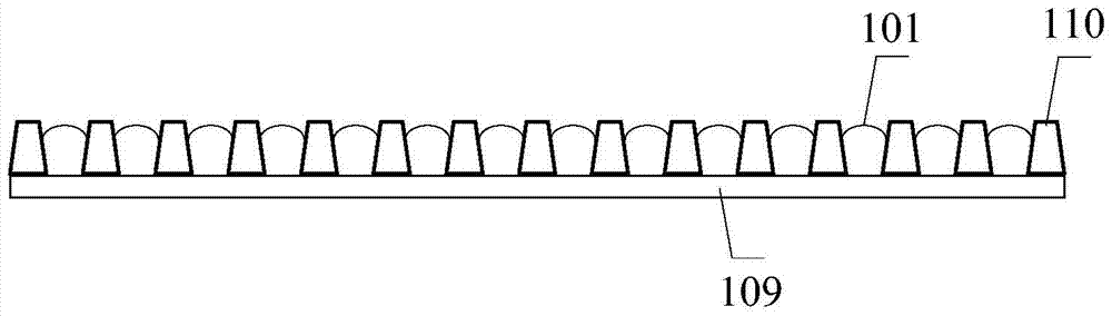
[0028] see Figure 5 , the embodiment of the present invention provides a transfer printing plate, including a base film 1 and a dot array composed of a plurality of dots 2 located on the base film 1, the base film 1 is divided into an active area 3 and an inactive area 4 surrounding the active area , the active area 3 corresponds to the liquid crystal display area; wherein, the dot array in the active area 3 has a first dot angle, and the dot array in the inactive area 4 has a secon...


PUM


Abstract

The present disclosure provides a transfer plate. The transfer plate includes a base film, and a dot array arranged on the base film and consisting of a plurality of dots. The base film includes an active region corresponding to a display region and a non-active region surrounding the active region. The dot array at the active region is of a first dot angle, and the dot array at the non-active region is of a second dot angle less than the first dot angle.

Description

technical field [0001] The invention relates to the field of display technology, in particular to a transfer printing plate. Background technique [0002] In the manufacturing process of Thin Film Transistor Liquid Crystal Display (TFT-LCD), it is necessary to coat a layer of alignment agent on the glass substrate of the liquid crystal cell to form a uniform alignment film, which makes the coating The liquid crystal molecules on it are arranged along a certain direction, and the liquid crystal molecules are deflected according to the specified direction according to the control of the electric field, so that the liquid crystal display panel finally including the liquid crystal cell can display normally. [0003] Among them, the process of forming an alignment film on a glass substrate is as follows: figure 1 As shown, first, the alignment agent 101 is dripped to the contact position between the cot roller 103 and the scraper 104 through the dispenser 102, and then the align...

Claims


Application Information

Patent Timeline
Patent Type & Authority Patents(China)
IPC IPC(8): G02F1/1337
CPCG02F1/1303G02F1/1337G02F1/133784
Inventor 郑先锋金相旭张建政程晋燕
Owner HEFEI BOE OPTOELECTRONICS TECH
Why Eureka
Try Eureka