Control device and control method of plate combiner

A technology of control device and control method, which is applied in the direction of program control and electrical program control in sequence/logic controllers, can solve problems such as large dust and chaotic boards during operation, and achieve stable operation, reduced quantity, and avoiding chaotic The effect of the plate phenomenon

Active Publication Date: 2015-01-28
HUAINAN BEIXIN BUILDING MATERIAL +1
View PDF7 Cites 3 Cited by
  • Summary
  • Abstract
  • Description
  • Claims
  • Application Information

AI Technical Summary

Problems solved by technology

[0003] Since the first, second, and third photoelectric switches are all installed under the combining machine, the three photoelectric switches are illuminated from bottom to top. During the pro

Method used


Image

  • Control device and control method of plate combiner

Examples


Embodiment Construction

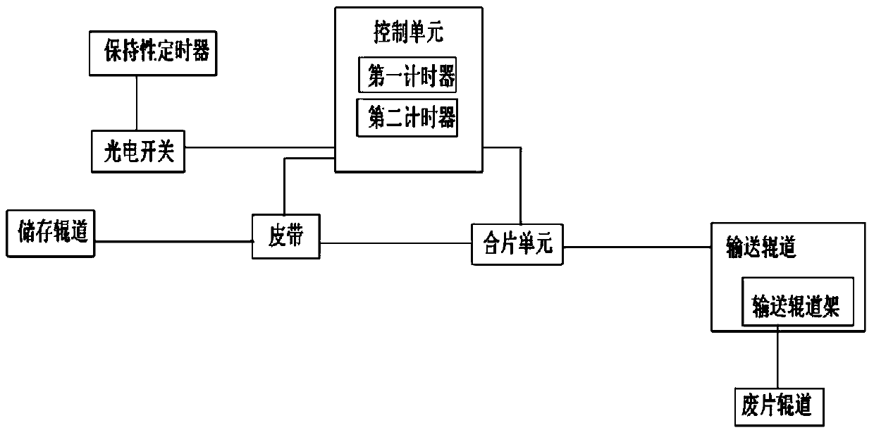
[0015] Such as figure 1 As shown, the control device of this laminator includes a photoelectric switch, a retentive timer, and a control unit; the photoelectric switch is installed above the storage roller table of the laminator; the retentive timer records from the photoelectric switch The time t0 from sensing the board to the belt of the combining machine starts to decelerate, the time t1 from the photoelectric switch sensing the board to the stop of the belt of the combining machine, the time t2 from the photoelectric switch sensing the board to the operation of the combining machine; the control unit They are respectively connected to the photoelectric switch, the belt, and the assembling unit; the control unit includes a first timer, which starts timing when the photoelectric switch senses a plate, and when t0 is reached, the control unit controls the belt to decelerate, and when t1 is reached, the control unit controls the belt to stop , when t2 is reached, the control u...


PUM


Abstract

The invention discloses a control device of a plate combiner. The number of optoelectronic switches adopted by the control device is reduced and the structure of the control device is simple, and therefore, the phenomenon of plate disorder due to wrong induction of the optoelectronic switches is avoided and stable operation of the plate combiner is guaranteed. The control device comprises an optoelectronic switch, a hold-down timer and a control unit, wherein the optoelectronic switch is mounted above the storage roller way of the plate combiner; the hold-down timer is used for recording the time t0 from the moment that the optoelectronic switch senses one plate to the moment that the belt of the plate combiner starts decelerating, the time t1 from the moment that the optoelectronic switch senses one plate to the moment that the belt of the plate combiner stops moving and the time t2 from the moment that the optoelectronic switch senses one plate to the moment that the plate combiner begins running; the control unit is connected with the optoelectronic switch, the belt and a plate combination unit, respectively; the control unit comprises a first timer which begins timing when the optoelectronic switch senses one plate; when the time of the first timer reaches t0, the control unit controls the belt to decelerate, when the time of the first timer reaches t1, the control unit controls the belt to stop, and when the time of the first timer reaches t2, the control unit controls the plate combination unit to reverse. The invention also provides a control method.

Description

technical field [0001] The invention belongs to the technical field of electromechanical equipment, and in particular relates to a control device of a lamination machine and a control method using the device. Background technique [0002] The operation (turnover) of the existing film combining machine system is controlled by three photoelectric switches below the film combining machine. The control process is as follows: when the first photoelectric switch senses a board, the belt starts to decelerate; when both the second photoelectric switch and the third photoelectric switch sense a board, the belt stops after a delay of 0.02 seconds; when the second photoelectric switch and the third photoelectric switch The switches are all sensed by the board and the composite machine is started with a delay of 0.05 seconds. [0003] Since the first, second, and third photoelectric switches are all installed under the combining machine, the three photoelectric switches are illuminated...

Claims


Application Information

Patent Timeline
IPC IPC(8): G05B19/04
CPCG05B19/04
Inventor 宋世恒
Owner HUAINAN BEIXIN BUILDING MATERIAL
Why Eureka
Try Eureka