Automatic terminal crimping machine

A crimping machine and terminal technology, which is applied in connection, electrical components, circuits, etc., can solve the problems of poor connection, poor product quality, poor electrical contact of the crimping part, etc., and achieve a fast and efficient crimping process. The effect of improving product competitiveness and improving crimping yield

Active Publication Date: 2015-01-28
GUANGDONG ZHONGDE CABLE
View PDF7 Cites 3 Cited by
  • Summary
  • Abstract
  • Description
  • Claims
  • Application Information

AI Technical Summary

Problems solved by technology

Because the crimping machine in the prior art is manually operated, not only the crimping efficiency is very low, but also consumes a lot of manpower, and the crimping force is not easy to control, which often leads to poor electrical contact between the conductor of the cable and the crimping part of the terminal, seriously affecting Product quality, especially the process of manually inserting the conductor of the cable into the terminal. Due to the small hole diameter of the terminal, it is difficult to penetrate directly manually, and it is easy to penetrate in place, resulting in low production efficiency and poor product consistency.

Method used


Image

  • Automatic terminal crimping machine
  • Automatic terminal crimping machine
  • Automatic terminal crimping machine

Examples


Embodiment Construction

[0032] The present invention is further described in conjunction with the following examples.

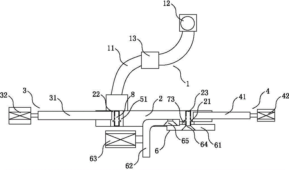
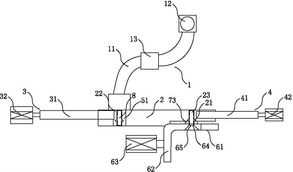
[0033] The specific implementation of a terminal automatic crimping machine created by the present invention is as follows: Figure 1 to Figure 4 As shown, it includes a frame, and a feeding device 1, a pushing device 3, a reverse material device 4, a reverse material blanking device 5, a clamping device 6 and a crimping device 7 arranged on the frame. A feeding chute 2 is provided, and a feeding position 22 and a crimping position 23 are arranged side by side on the feeding chute 2. The terminal automatic crimping machine in this embodiment also includes a controller.

[0034] The feeding device 1 comprises a feeding pipe 11 and a feeding hopper 12, one end of the feeding pipe 11 is connected to the feeding hopper 12, and the other end of the feeding pipe 11 is connected to the feeding position 22 of the feeding chute 2 of the frame. The material pipe 11 is provided with an air bl...


PUM


Abstract

The invention relates to an automatic terminal crimping machine which structurally comprises a machine frame and a feeding device, a pushing device, a return material retreating device, a return material blanking device, a clamping device and a crimping device which are arranged on the machine frame. In the crimping process, a terminal enters the feeding position through a feeding pipe of the feeding device, and meanwhile the pushing rod pushes the terminal to the crimping position along a feeding slide. When the direction of the terminal is correct, a conductor of a cable is inserted into the crimping portion of the terminal, then an upper clamping plate and a lower clamping plate clamp the terminal in a fastening mode, and then an upper press die moves downwards to be matched with a lower press die to extrude and deform the crimping portion of the terminal to achieve crimping molding. When the direction of the terminal is wrong, a return material retreating rod pushes the terminal to the return material blanking plate, meanwhile the return material blanking plate moves to enable the terminal to fall into a recycling device below a support. The machine can greatly improve the crimping efficiency, saves time and labor, improves the crimping yield and improves product competitiveness.

Description

technical field [0001] The invention relates to the technical field of crimping machines, in particular to a terminal automatic crimping machine applied to cable terminals. Background technique [0002] The end of the cable is generally crimped with a terminal, and the conductor of the cable is electrically connected to the crimping part of the terminal. The cable with the terminal can be used as a power distribution component for power supply or signal transmission of various devices. widely used. [0003] In the prior art, the crimping process of cable terminals generally includes: firstly, manually inserting the conductor of the cable wire into the crimping part of the terminal, then placing the terminal on the lower pressing film of the crimping machine, and finally manually operating the crimping part. The connection machine makes the upper pressing film press down to squeeze and deform the crimping part of the terminal, so that the conductor of the cable and the crim...

Claims


Application Information

Patent Timeline
Patent Type & Authority Applications(China)
IPC IPC(8): H01R43/055
CPCH01R43/055
Inventor 刘发义邓伟键谭春红彭仕旋
Owner GUANGDONG ZHONGDE CABLE
Why Eureka
Try Eureka