
An environment-friendly prefabricated double-box deep-hole drainage well and its construction method
A technology of drainage wells and deep holes, applied in drainage structures, chemical instruments and methods, water supply devices, etc., to achieve the effect of protecting the environment, shortening the construction period, and reducing the construction process
- Summary
- Abstract
- Description
- Claims
- Application Information
AI Technical Summary
Problems solved by technology
Method used
Image

Examples
Embodiment 1
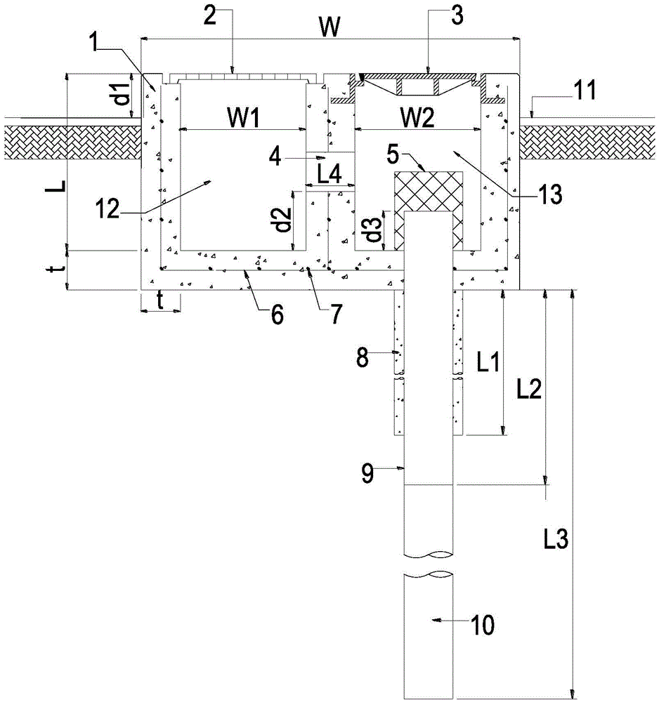
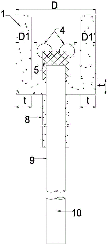
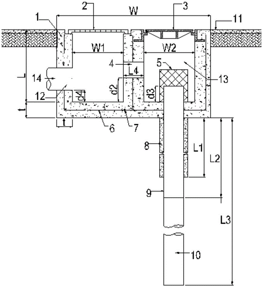
[0110] An environmentally friendly prefabricated double-box deep-hole drainage well, including a sediment tank for receiving rainwater or road surface water and sedimentation, and a drainage tank for receiving water treated with sediment in the sediment tank and discharging it into the ground. The room is connected through a connecting pipe. The roof of the sediment tank is provided with a grid-style well cover, the roof of the drainage tank is provided with a closed manhole cover, and the bottom of the drainage tank is provided with a drainage hole directly reaching the groundwater layer, and a drainage pipe is provided in the drainage hole. A mortar retaining wall is arranged between the drain hole and the drain pipe. The upper end of the drain hole is higher than the bottom of the drain tank. The connecting pipe is arranged horizontally, and the horizontal position of the connecting pipe is higher than that of the sediment tank and the bottom of the drainage tank. Both the...
Embodiment 2
[0123] The manhole cover on the top of the sediment tank is a 760*760mm square grid manhole cover, the manhole cover on the top of the drainage tank is a circular manhole cover with a diameter of 600mm, and the drainage well is located in the detention tank.
[0124] The remaining parameters are the same as in Example 1. Since the drainage well is located in the detention pond, the top of the drainage well should be higher than the bottom of the pond, so as to prevent a large amount of residue from entering the drainage well with the water flow, causing serious deposition and increasing the burden of dredging. So design d1=230mm.
[0125] In addition, this example does not need to be provided with a conveying drainage pipe, so there is no need to perforate the drainage well wall.
PUM
 Abstract
Description
Claims
Application Information