Optical fiber connector and optical fiber connector assembly using the optical fiber connector

An optical fiber connector and contact technology, applied in the field of optical fiber connectors and connector components, can solve the problems of bending guide pins, weak anti-vibration and shock resistance of optical fiber connectors, affecting the use of connectors, etc. bit effect

Inactive Publication Date: 2017-01-04
CHINA AVIATION OPTICAL-ELECTRICAL TECH CO LTD
View PDF1 Cites 2 Cited by
  • Summary
  • Abstract
  • Description
  • Claims
  • Application Information

AI Technical Summary

Problems solved by technology

The problem with the existing optical fiber connector is that the diameter of the guide pin is small, so it is generally impossible to achieve one-time alignment, which leads to the inability of the connector to achieve blind mating. When the guide pin and the guide pin hole are not aligned. When the plug and socket are inserted, it is likely to bend the guide pin and affect the use of the connector; in addition, only rely on the cooperation of the guide pin and the guide pin hole to prevent the radial relative movement of the plug MT contact and the socket MT contact. Vibration and shock resistance of the entire fiber optic connector is not strong, because a slight vibration and shock, vibration and shock will cause the plug MT contact and socket MT contact to have a large displacement in the radial direction, affecting The quality of signal transmission ultimately leads to the fact that the entire fiber optic connector cannot be used in harsh environments such as outdoors

Method used


Image

  • Optical fiber connector and optical fiber connector assembly using the optical fiber connector
  • Optical fiber connector and optical fiber connector assembly using the optical fiber connector
  • Optical fiber connector and optical fiber connector assembly using the optical fiber connector

Examples


Embodiment Construction

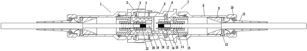
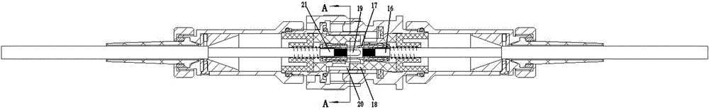
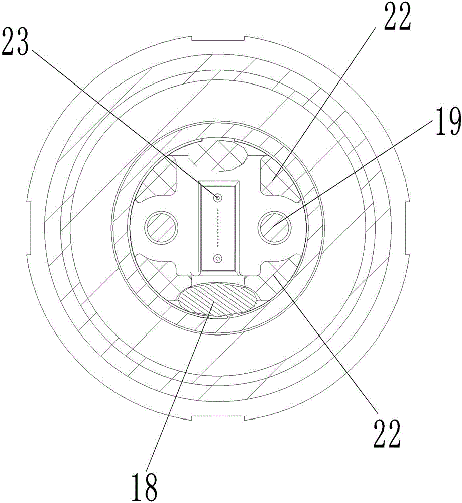
[0028] Examples of fiber optic connector assemblies are Figure 1~11 Shown: including plug 1 and socket 7, the plug and socket are circular connectors, the plug includes a plug housing 4 with the front end as the insertion end, the socket includes the socket housing 5 with the front end as the insertion end, and the plug housing 4 passes through The plug fixing part is fixed with a plug MT contact part 21 having a guide pin hole 23, and a socket MT contact part 16 having a guide pin 17 is fixed in the socket housing through the socket fixing part, and the plug MT contact part 21 and the socket MT contact part 16 are both It belongs to the prior art, and its specific structure is no longer described in detail. The plug housing 4 is screwed with a connecting nut 2, the socket housing 5 is provided with an external thread that matches the connecting nut, and the socket housing is provided with a socket housing that limits the tightening limit of the connecting nut along the tight...


PUM


Abstract

The invention relates to an optical fiber connector and an optical fiber connector assembly using the optical fiber connector. The optical fiber connector includes a housing whose front end is a plug-in end, and an MT contact piece having a guide pin hole or a guide pin is fixed in the housing through a fixing member. The housing or the fixing part is provided with a positioning hole / positioning post for positioning and anti-rotation inserting with the positioning post / positioning hole on the adapted optical fiber connector before the guide pin hole and the guide pin are inserted. The guide pin hole / guide pin inserted into the guide pin / guide pin hole on the adapted fiber optic connector after the positioning hole and the positioning post are positioned and inserted, the diameter of the guide pin hole on the fiber optic connector / the diameter of the guide pin Larger than the hole diameter of the guide pin hole / diameter of the guide pin. The invention provides an optical fiber connector capable of realizing blind insertion and being used in a vibration and shock environment and an optical fiber connector assembly using the optical fiber connector.

Description

technical field [0001] The invention relates to an optical fiber connector and a connector assembly using the optical fiber connector. Background technique [0002] In order to achieve high-density transmission of optical signals, fiber optic connectors using MT contacts (ie, multi-channel contacts) are becoming more and more widely used. Existing fiber optic connectors using such MT contacts are disclosed in Chinese patent CN203720411U "a A kind of modular fiber optic connector", the fiber optic connector includes a plug and a socket, because the plug and the socket are compatible with each other, so the plug and the socket can also be called a fiber optic connector and an adapted fiber optic connector, the plug includes a plug housing , the socket includes a socket housing, the socket MT contact is installed in the plug housing through the jack fixing part, and the plug MT contact is installed in the socket housing through the pin fixing part, and the socket MT contact and...

Claims


Application Information

Patent Timeline
Patent Type & Authority Patents(China)
IPC IPC(8): G02B6/38
Inventor 余永强周生贺刘乃常
Owner CHINA AVIATION OPTICAL-ELECTRICAL TECH CO LTD
Why Eureka
Try Eureka