Lightning protection device

A lightning protection device and lightning current technology, applied in overvoltage arresters, electrical components, spark gaps and other directions using spark gaps, can solve the problems of reduced lightning protection performance, affecting service life, long arc extinguishing time, etc., to achieve flashover The effect of arc extension, good insulation effect and short arc extinguishing time

Active Publication Date: 2016-04-27
GUANGDONG ELECTRIC POWER SCI RES INST ENERGY TECH CO LTD
View PDF3 Cites 1 Cited by
  • Summary
  • Abstract
  • Description
  • Claims
  • Application Information

AI Technical Summary

Problems solved by technology

The multi-series gap lightning protection device uses the characteristics of the gap arc in the high-voltage technology for lightning protection design. However, in the existing gap lightning protection device, the arc extinguishing time is long, which may easily cause the system to trip due to the relay protection action; The gas material generates gas driving force to complete the elongation, cooling and extinguishing of the arc
After multiple lightning strikes and flashovers, the lightning protection performance of the device will decrease with the consumption of materials, which will affect the service life

Method used


Image

  • Lightning protection device
  • Lightning protection device
  • Lightning protection device

Examples


Embodiment 1

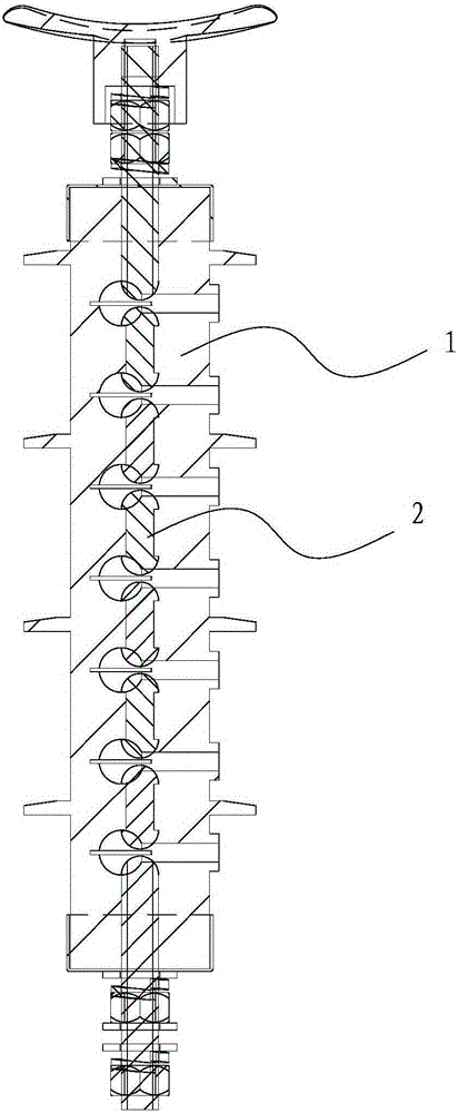
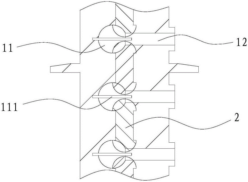
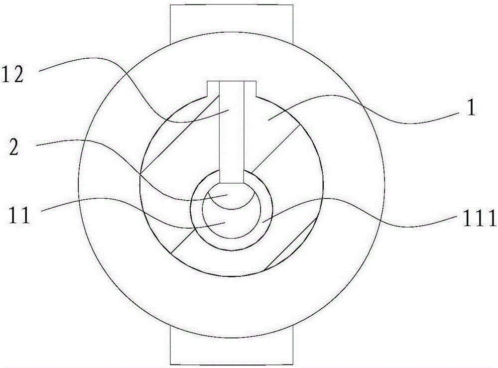
[0032] Such as Figures 1 to 3 As shown, in this embodiment, the lightning protection device includes an insulating silicon-fluorine colloid shell 1 and electrodes 2, the insulating shell 1 is rod-shaped, and has an arc extinguishing chamber 11 and an electrode 2 chamber, and the arc extinguishing chamber 11 and the electrode 2 chamber 1. The internal axial lines are staggered, and the arc extinguishing chamber 11 communicates with two adjacent electrode 2 chambers, and the electrode 2 chamber communicates with two adjacent arc extinguishing chambers 11.

[0033] There are several electrodes 2, and the two ends of the electrodes 2 are two lightning-connecting surfaces, which are used to connect the arc when struck by lightning. The electrode 2 is placed in the electrode 2 chamber, and the lightning receiving surfaces are respectively exposed to the arc extinguishing chambers 11 adjacent to the electrode 2 chamber, so that the two adjacent arc extinguishing chambers 11 are elec...

Embodiment 2

[0058] The difference between embodiment two and embodiment one is:

[0059] like Figures 5 to 7 As shown, the buffer groove 221 is provided on the cylindrical surface of the connecting portion 22 .


PUM


Abstract

The invention relates to a lightning protection device which comprises a shell and electrodes. Arc extinguishing chambers and at least two electrode chambers are formed in the shell, the inner-wall surface of each arc extinguishing chamber is round and smooth, the arc extinguishing chambers and the electrode chambers are arranged in a staggered manner, each arc extinguishing chamber is provided with two openings which are communicated with the two adjacent electrode chambers respectively, and each arc extinguishing chamber is communicated with the outside through an arc blowing passage; a lightning receiving face is arranged at each of two ends of each electrode, the electrodes are placed in the electrode chambers, the lightning receiving faces at the two ends of the electrodes are exposed in the arc extinguishing chambers on two sides of the electrode chambers at the same time to communicate the arc extinguishing chambers on the two sides, and a flashover gap is reserved between the two lightning receiving faces in each arc extinguishing chamber. The lightning protection device is free of charge accumulation effect, less prone to being broken down under identical gap voltage and capable of improving line insulation level; especially when being on a high-voltage power distribution line network, influence on power distribution quality caused by voltage fluctuation of the power distribution network due to great lowering of voltage of the power distribution network because of frequent misoperation discharging of the lightning protection device can be avoided.

Description

technical field [0001] The patent of the present invention relates to the technical field of lightning protection for high-voltage transmission lines in power systems, and in particular to a lightning protection device. Background technique [0002] With the continuous and in-depth research on lightning protection devices for power system lines, the application of various new lightning protection devices is changing with each passing day. The multi-series gap lightning protection device uses the characteristics of the gap arc in the high-voltage technology for lightning protection design. However, in the existing gap lightning protection device, the arc extinguishing time is long, which may easily cause the system to trip due to the relay protection action; The gas material generates gas driving force to complete the elongation, cooling and extinguishing of the arc. After multiple lightning strikes and flashovers, the lightning protection performance of the device will decr...

Claims


Application Information

Patent Timeline
Patent Type & Authority Patents(China)
IPC IPC(8): H01T4/02H01T4/16
Inventor 李恒真武利会孔华东张璐苏杏志张鸣胡聪陈斯翔王云飞
Owner GUANGDONG ELECTRIC POWER SCI RES INST ENERGY TECH CO LTD
Why Eureka
Try Eureka