Broaching tool mechanism capable of rotating at high speed

A high-speed rotation, bearing seat technology, used in grinding machine parts, other manufacturing equipment/tools, grinding/polishing equipment, etc., can solve problems such as inability to achieve sealing effect, wear of sealing rings, heat at the sealing area, etc. Achieve the effect of reducing labor input, high rotation, and reducing load

Inactive Publication Date: 2018-11-06
KEDE NUMERICAL CONTROL CO LTD
View PDF10 Cites 0 Cited by
  • Summary
  • Abstract
  • Description
  • Claims
  • Application Information

AI Technical Summary

Problems solved by technology

The problem is that when the seal rotates relative to another part, the seal will generate heat due to the large resistance of the rubber to the rotating surface. When it operates at high speed, the temperature will rise rapidly, and the seal ring will Destroys rapidly at high temperatures, causing pressure drop and media leakage
The sealing ring has a speed limit, the speed is very low, the sealing ring is worn during the rotation process, the sealing effect cannot be achieved, and the service life is short
Moreover, the rotatable broach mechanism of the prior art contains two multi-layer gray ring seals, so the requirements for parts are very high

Method used


Image

  • Broaching tool mechanism capable of rotating at high speed
  • Broaching tool mechanism capable of rotating at high speed
  • Broaching tool mechanism capable of rotating at high speed

Examples


Embodiment Construction

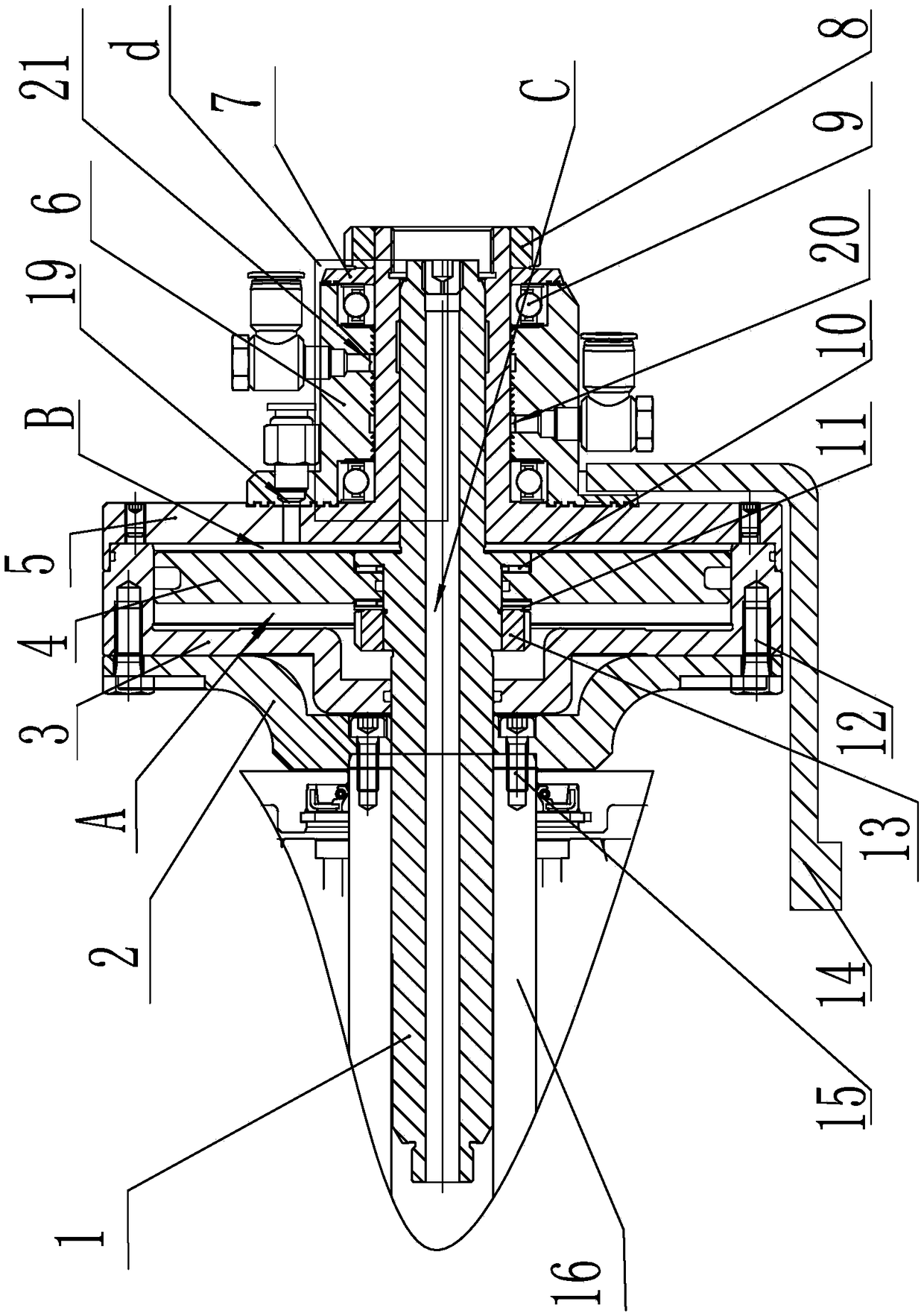
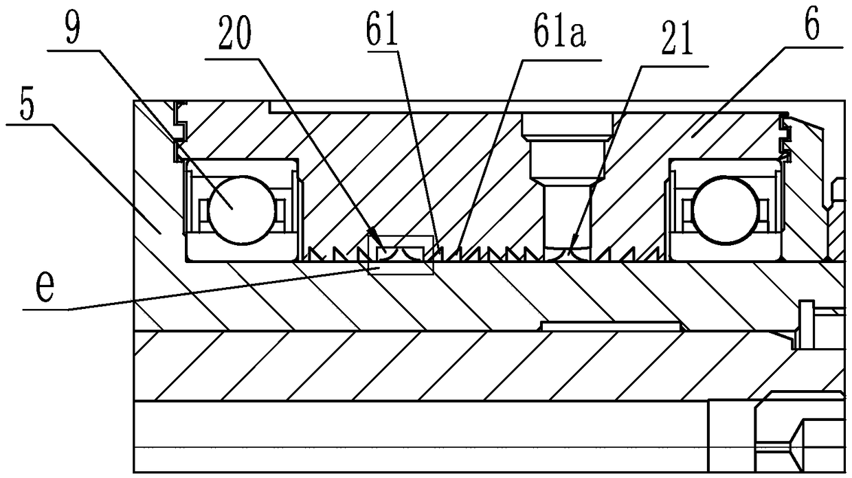
[0023] Such as figure 1 , figure 2 As shown, a high-speed rotating broach mechanism of the present invention comprises a cylinder-piston assembly in which a piston 4 is arranged inside an outer sleeve 3 and a support sleeve 5 with a T-shaped longitudinal section; the piston 4 passes through the central hole A rotary mandrel 1 is set, and the mandrel 1 passes through the outer casing 3 and the support sleeve 5 at both ends in a hermetic manner, and the support sleeve 5 is contacted by two corners respectively arranged at the two ends of the bearing seat 6. The bearing 9 is rotatably connected to the bearing seat 6, the distance between the outer wall of the cylindrical section of the support sleeve 5 and the inner wall of the bearing seat 6 and the distance between the right side wall of the support sleeve 5 and the bearing seat The distances between the left side walls of 6 are all 0.02-0.05 mm. Since the support sleeve 5 and the bearing seat 6 rotate relatively, the cleara...


PUM


Abstract

The invention discloses a broaching tool mechanism capable of rotating at high speed. Non-contact type seal is adopted to replace the traditional Glyd ring seal manner. A supporting sleeve is rotatably connected to a bearing pedestal through two angular contact bearings arranged on two ends of the bearing pedestal, the distance between the outer wall of the cylindrical segment of the supporting sleeve and the inner wall of the bearing pedestal and the distance between the right side wall of the supporting sleeve and the left side wall of the bearing pedestal are each 0.02 to 0.05 mm, three airsource joints are formed in a body of the bearing pedestal, air seal parts are arranged at the positions, on two sides of the three air source joints, of the inner wall and the side wall of the bearing pedestal, and the air seal parts are composed of multiple annular air seal grooves formed in the inner wall and the side wall of the bearing pedestal in parallel. Air enters the seal structure through the air source joints, vortex is generated in air in the air seal grooves, and air overflowing is prevented; high-speed functions are achieved, the mechanism has the rotating speed being 3000 rpmin the application of a five-axis tool grinding machine, and compared with 500 rpm in the prior art, the speed is improved by multiple times.

Description

technical field [0001] The invention relates to the field of mechanical manufacturing, in particular to a high-speed rotating broach mechanism. Background technique [0002] The existing broach mechanism is divided into two types, one is a non-rotatable standard cylinder type broach mechanism, and the other is a mechanical broach mechanism equipped with an expensive rotary joint, which is realized by disc spring or coil spring restoring force. Broaching action. [0003] After the air source of the standard cylinder, the axial extension and retraction can be realized through the forward and backward movement of the piston, but the rotation of the piston mandrel inside the cylinder cannot be realized, and there is no central air blowing function. [0004] The mechanical broach mechanism is used on most spindles, and the broach mechanism that needs to realize the rotary function on most spindles needs to be equipped with an expensive rotary joint. [0005] Previously, on July...

Claims


Application Information

Patent Timeline
Patent Type & Authority Applications(China)
IPC IPC(8): B24B3/00B24B41/00
CPCB24B3/00B24B41/005
Inventor 周吉贞张海波贺行健郭翠娟李亚鹏郭启栋邢玉麟
Owner KEDE NUMERICAL CONTROL CO LTD
Why Eureka
Try Eureka