Waste fiber and product pre-treatment system

A waste fiber and pretreatment technology, applied in grain processing, plastic recycling, recycling technology, etc., can solve the problems of fluffy waste silk, small bulk density, and different lengths of waste silk, so as to reduce load bearing, output and efficiency Fast, avoid uneven fracture effect

Active Publication Date: 2016-06-22
湖北绿宇环保有限公司
View PDF4 Cites 18 Cited by
  • Summary
  • Abstract
  • Description
  • Claims
  • Application Information

AI Technical Summary

Problems solved by technology

[0002] In the recycling process of waste fibers and products, it is first necessary to crush them. The existing crushing mechanism usually adopts a single-shaft rotary crushing method, which has problems such as different lengths of waste filaments after crushing and serious winding; Due to entrainment of a large amount of air and moisture in the waste silk, it usually leads to degradation in the subsequent extrusion and melting process; and the waste silk is fluffy in volume and low in bulk density, which restricts the efficiency of the recycling process

Method used


Image

  • Waste fiber and product pre-treatment system
  • Waste fiber and product pre-treatment system
  • Waste fiber and product pre-treatment system

Examples


Embodiment 1

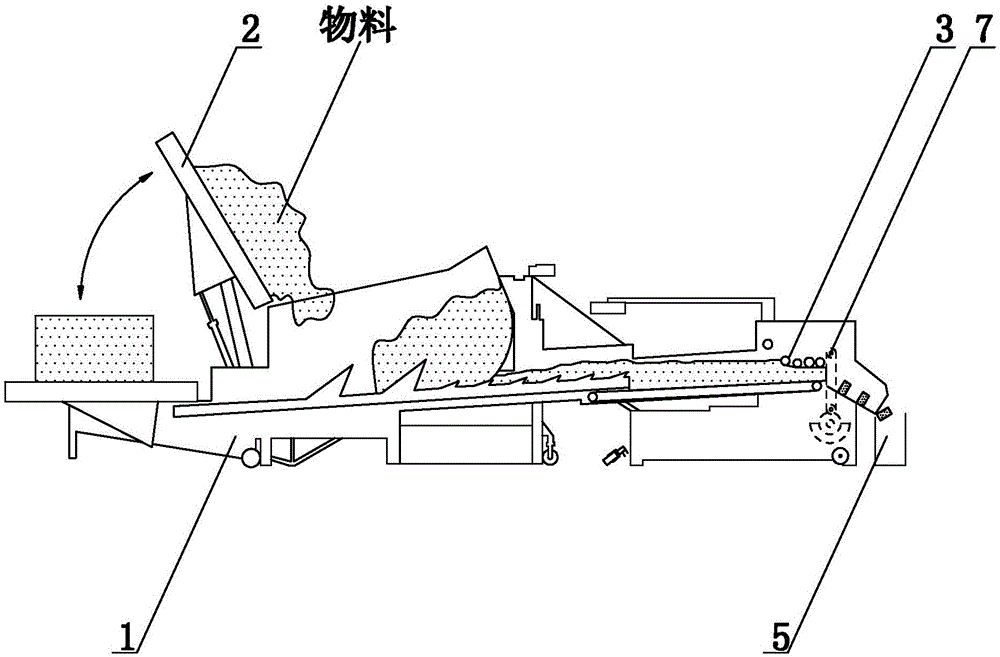
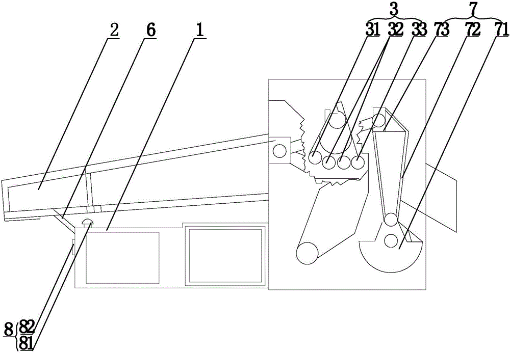
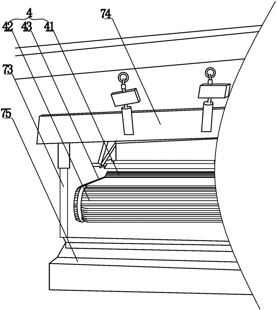
[0023] The fiber feeding silk system of this embodiment, combines figure 1 , including a frame 1, a hopper 2, a pressing roller 3, a wire feeding wheel 4, a compacting machine 5, a lifting arm 6 and a moving knife driving mechanism 7, the hopper 2 is located on the frame 1, and one end thereof is provided with a lifting arm 6, The other end is then positioned at the front of the pressing roller 3, and feeds the material for the pressing roller 3, combined with figure 2 , the wire feed wheel 4 comprises an upper wire feed wheel 41, a lower wire feed wheel 42 and a conveyer belt 43 between the upper wire feed wheel 41 and the lower wire feed wheel 42, and the upper wire feed wheel 41 and the lower wire feed wheel 42 are located at The pressing roller 3 rear is connected by a conveyor belt 43 between the two, and the moving knife driving mechanism 7 includes a motor, an eccentric wheel 71, a transmission belt 72, a knife rest 73, a fixed knife 75 and a moving knife 74, and the m...

Embodiment 2

[0027]The setting and working principle of this embodiment and embodiment 1 are the same, the difference is that: the moving knife driving mechanism 7 includes a motor, an eccentric wheel 71, a transmission belt 72 and a knife rest 73, and the moving knife 5 is installed on the frame 1 through the knife rest 73, The motor drives the eccentric wheel 71 to rotate, and the eccentric wheel 71 drives the knife rest 73 and the movable knife 5 to reciprocate up and down through the transmission belt 72; One end is gradually separated from the cutter head 51, which is beneficial to the compaction process while accelerating the mixing speed of the broken section and increasing its kinetic energy.

Embodiment 3

[0029] The setting and working principle of this embodiment are the same as that of Embodiment 1, the difference is that a fall-limiting mechanism 9 is set between the hopper 2 and the frame 1, and the fall-limiting mechanism 9 is an upwardly protruding top column 91 on the frame 1. The top column 91 is located below the hopper 2; the top column 91 is arranged between the hopper 2 and the frame 1, and the top column 91 is located behind (inside) the lifting arm 8. On the one hand, it plays a supporting role and reduces the load bearing of the lifting arm 8. On the other hand, it also acts as a limit, preventing the hopper 2 from falling excessively and damaging the frame 1, and avoiding the hopper 2 from turning over.


PUM


Abstract

The invention relates to a waste fiber and product pre-treatment system, and belongs to the technical field of wire rod machining. The waste fiber and product pre-treatment system comprises a rack, a hopper, a material pressing roller, wire feeding wheels, a power driving mechanism and a compression compaction machine; the hopper is located on the rack, one end of the hopper is provided with a lifting arm, and the other end of the hopper is located in front of the material pressing roller, and the hopper supplies materials to the material pressing roller; the wire feeding wheels comprise an upper wire feeding wheel and a lower wire feeding wheel, and the upper wire feeding wheel and the lower wire feeding wheel are both located behind the material pressing roller and connected though a conveying belt; the power driving mechanism comprises a motor, an eccentric gear, a transmission belt, a knife rest, a fixed cutter and a movable cutter; and the compression compaction machine is located behind the movable cutter. The waste fiber and product pre-treatment system is applied to cutting pre-treatment of waste like waste silks, and has the beneficial effects of being less in energy dissipation, high in efficiency and the like.

Description

technical field [0001] The invention relates to a pretreatment system for waste fibers and products, belonging to the technical field of recycling waste fibers and products. Background technique [0002] In the recycling process of waste fibers and products, it is first necessary to crush them. The existing crushing mechanism usually adopts a single-shaft rotary crushing method, which has problems such as different lengths of waste filaments after crushing and serious winding; Because the waste silk entrains a large amount of air and moisture, it usually leads to the degradation of the subsequent extrusion and melting process; and the waste silk is fluffy and has a small bulk density, which restricts the efficiency of the recycling process. [0003] Based on this, this application is made. Contents of the invention [0004] In order to overcome the above-mentioned defects existing in the utilization process of existing waste fibers and products, the invention provides a w...

Claims


Application Information

Patent Timeline
Patent Type & Authority Applications(China)
IPC IPC(8): B29B17/00B29B17/04B02C18/02B02C18/04
CPCB29B17/0042B29B17/0412B29B2017/044Y02W30/62
Inventor 刘雄张朔姚强石教学
Owner 湖北绿宇环保有限公司
Why Eureka
Try Eureka