Roller type non-contact backstop

A non-contact, backstop technology, which is applied in clutches, one-way clutches, mechanical equipment, etc., can solve the problems of high precision machining of wedges, large running resistance, and reduced service life of backstops, etc., and is easy to achieve Processing and measurement, improving life and performance, and ensuring the effect of precise consistency

Inactive Publication Date: 2017-02-15
NINGXIA YUANCHEN TECH
View PDF7 Cites 0 Cited by
  • Summary
  • Abstract
  • Description
  • Claims
  • Application Information

AI Technical Summary

Problems solved by technology

The wedge backstop is used, and the wedge is in pressure contact with the inner and outer rings. When the mechanical transmission device rotates in the opposite direction, the direction of the wedge changes, so as to achieve the purpose of backstop; the backstop of this structure, the wedge When the block is running, there is always friction with the inner and outer rings, forming a large running resistance, and the contact is always in the same area. Long-term operation will cause large wear to this area, reducing its backstop performance
Therefore, the currently used backstop rotates the wedge for a long time to wear too much, and the backstop angle becomes smaller, which reduces the service life of the backstop and may cause serious accidents; Due to the impact of molds, batches, etc., it is difficult to ensure consistency

Method used


Image

  • Roller type non-contact backstop
  • Roller type non-contact backstop
  • Roller type non-contact backstop

Examples


Embodiment Construction

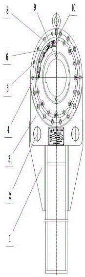
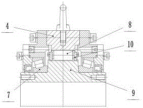
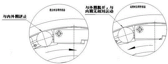
[0016] combined with figure 1 , attached figure 2 And attached image 3 To illustrate, the roller type non-contact backstop of the present invention consists of arm 1, bearing pin 2, side plate 3, outer ring 4, extension spring 5, cage 6, bearing 7, roller 8, inner ring 9 and The baffle plate 10 is composed of the arm 1 and the side plate 3 on the main body of the backstop through the pin shaft 2, the side plate 3 is connected with the outer ring 4, and the internal cage 6 is installed on the outer ring 4 and the inner ring 9 formed In the space, the inner ring 9 is installed on the shaft extension of the transmission device, and a plurality of backstop planes are evenly distributed on the inner ring 9, and the roller 8 is in contact with the outer ring 4, and is arranged in the space between the outer ring 4 and the inner ring 9 backstop planes. A plurality of rollers 8 are evenly positioned in the groove and through the cage 6, and the radial and axial movable spaces of t...


PUM


Abstract

The invention relates to a roller type contactless non-return device, in particular to a non-return device used for preventing a transmission device from reversing in a mechanical transmission device. When the non-return device normally runs, an inner ring 9 rotates, and a baffle plate 10 drives a retainer to simultaneously run in the same direction as rollers 8. When the non-return device is non-return, a transmission shaft can drive the inner ring 9 to reversely run, and the retainer 6 is pulled by the action force of a tension spring 5 to drive the rollers 8 to reversely run; a ratchet wheel surface of the inner ring 9 oppresses the rollers 8 to transfer torque to an outer ring 4 to cause maximum positive pressure, and the retainer ensures that the positions of a plurality of rollers 8 are the same; the reverse torque of the outer ring 4 enables the rollers not to loosen, the contact surfaces of the rollers have maximum friction, and the non-return effect is achieved. The invention provides the non-return device which is uniform in stress, high in non-return speed, low in abrasion, low in running resistance and long in service life.

Description

[0001] Technical field: [0002] The roller type non-contact backstop of the invention relates to a backstop used in a mechanical transmission device for preventing the transmission device from reversing. [0003] Background technique: [0004] At present, the backstop commonly used in China is mainly composed of outer ring, inner ring, wedge, roller and moment arm. The wedge backstop is used, and the wedge is in pressure contact with the inner and outer rings. When the mechanical transmission device rotates in the opposite direction, the direction of the wedge changes, so as to achieve the purpose of backstop; the backstop of this structure, the wedge When the block is running, there is always friction with the inner and outer rings, forming a large running resistance, and the contact is always in the same area. Long-term operation will cause large wear to this area, reducing its backstop performance. Therefore, the currently used backstop rotates the wedge for a long time to...

Claims


Application Information

Patent Timeline
Patent Type & Authority Patents(China)
IPC IPC(8): F16D41/064
Inventor 曾顺利袁峰苏小平李嘉麟任鹏张鹏
Owner NINGXIA YUANCHEN TECH
Why Eureka
Try Eureka