
Copper pipe side-by-side automatic bending device

A bending device and copper tube technology, applied in the field of pipe bending, can solve the problems of high labor intensity and affect production efficiency, and achieve the effect of increasing production efficiency

Pending Publication Date: 2020-08-07
GREE ELECTRIC APPLIANCES ZHENGZHOU +1
View PDF10 Cites 2 Cited by
  • Summary
  • Abstract
  • Description
  • Claims
  • Application Information

AI Technical Summary

Problems solved by technology

[0003] At present, the existing production method is to manually remove a pack of shunt copper pipes, take out one into a simple bending tool, and bend it into a 90-degree right angle. Only a single bend can be performed, which affects production efficiency.
In addition, employees manually operate simple bending tools to bend tens of thousands of copper pipes, which is labor-intensive. Therefore, it is necessary to apply automation technology to solve these problems when automated production is becoming more and more common.

Method used


Image

  • Copper pipe side-by-side automatic bending device
  • Copper pipe side-by-side automatic bending device
  • Copper pipe side-by-side automatic bending device

Examples


Embodiment 1

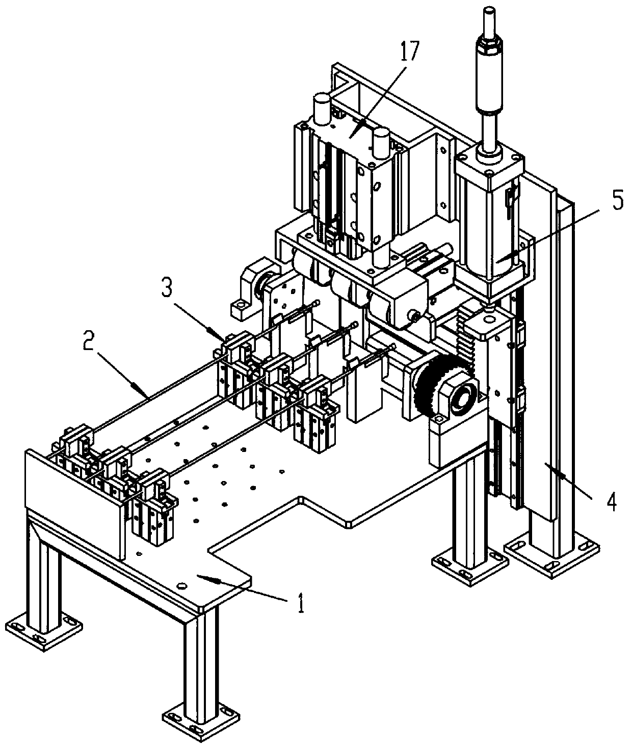
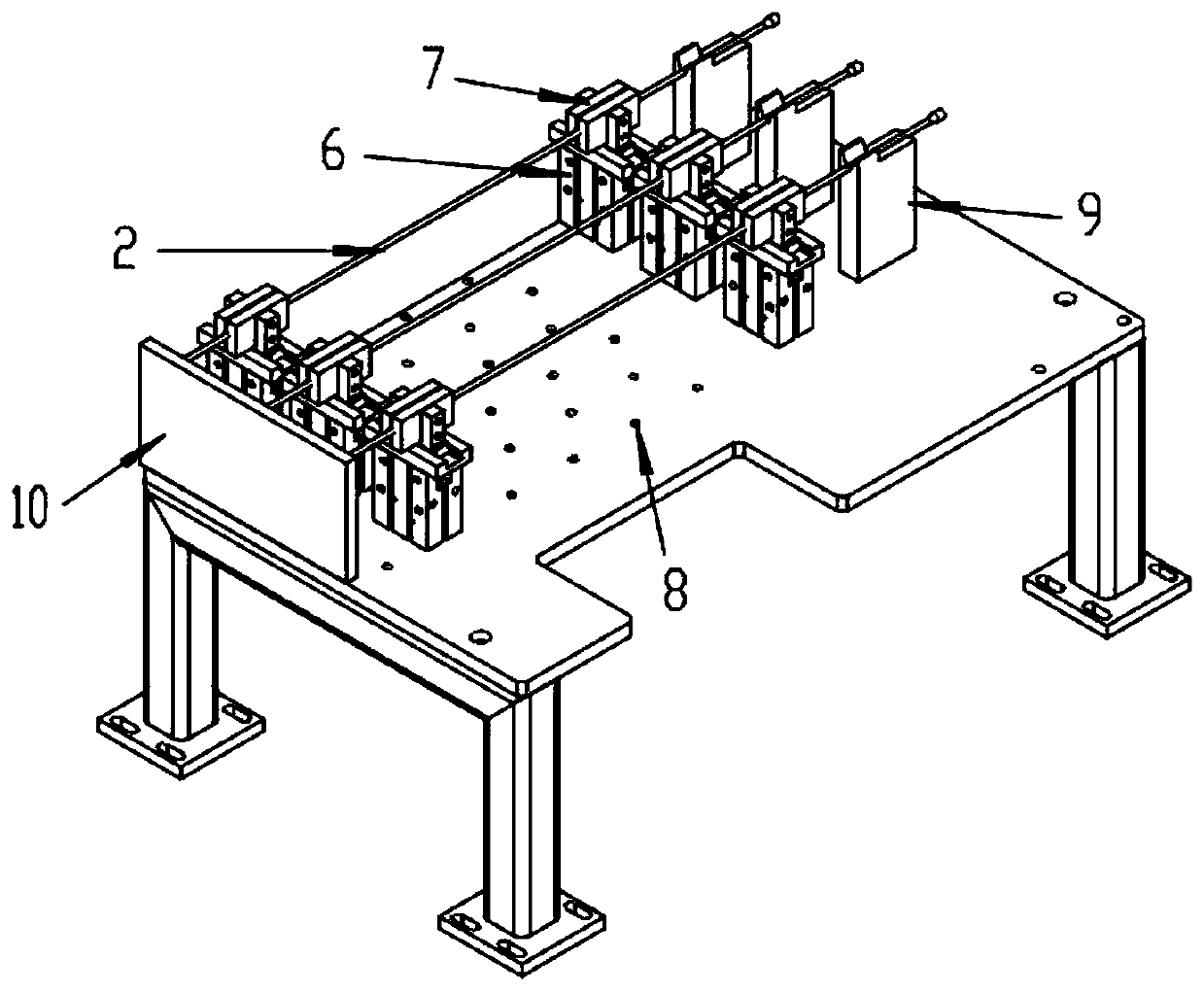
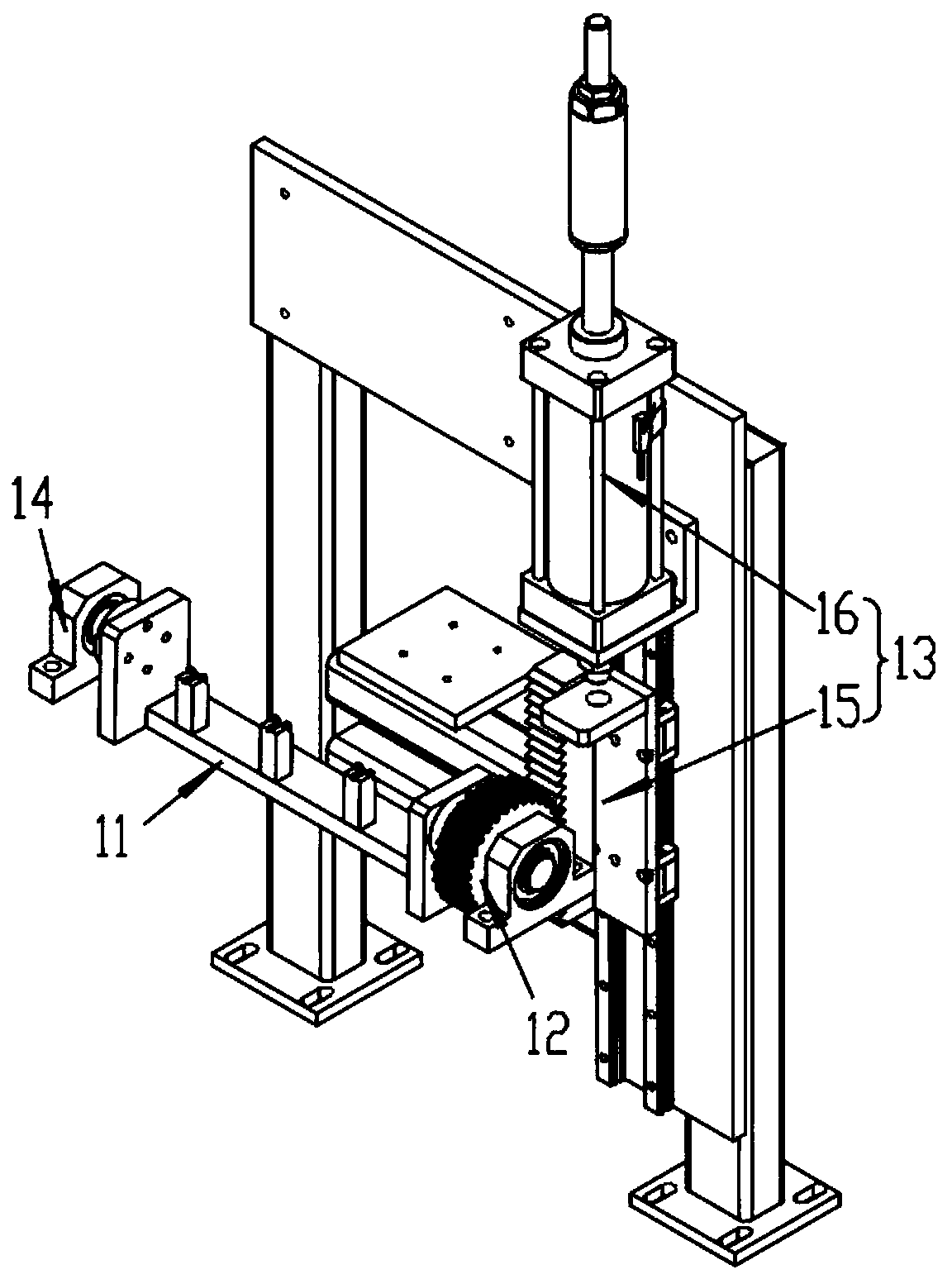
[0026] A kind of parallel automatic bending device for copper tubes of this embodiment, such as Figure 1-4 As shown, it includes a first mounting bracket 1, the top of the first mounting bracket 1 is fixed with an arrangement and positioning mechanism 3 for arranging and positioning a plurality of copper pipes 2, and the tail of the arrangement and positioning mechanism 3 is fixed with a second mounting bracket 4. The second mounting bracket 4 is fixed with an automatic bending mechanism 5 capable of adjusting the bending angles of multiple copper pipes 2 . The alignment and positioning of multiple copper tubes 2 is realized by arranging the positioning mechanism 3, which is convenient for the automatic bending mechanism 5 at the tail of the positioning mechanism 3 to perform automatic bending processing on multiple copper tubes 2 at the same time, realizing the simultaneous bending of multiple copper tubes 2 Bending processing, suitable for fast production rhythm and high ou...

Embodiment 2

[0038] The other structures of this embodiment are the same as those of Embodiment 1, except that the driving method of the rack assembly used in Embodiment 1 can be changed to an electric actuator to adapt to automatic switching and adjustment of the bending angle of the copper pipe.


PUM


Abstract

The invention discloses a copper pipe side-by-side automatic bending device and relates to the technical field of pipeline bending. The device comprises a first mounting bracket, the top end of the first mounting bracket is fixedly provided with an arranging and positioning mechanism for arranging and positioning a plurality of copper pipes, the tail part of the arranging and positioning mechanismis fixedly provided with a second mounting bracket, and the second mounting bracket is fixedly provided with an automatic bending mechanism capable of adjusting bending angles of the copper pipes. According to the copper pipe side-by-side automatic bending device, arrangement and positioning of the copper pipes are realized through the arranging and positioning mechanism, the automatic bending mechanism at the tail part of the arranging and positioning mechanism conveniently performs automatic bending treatment on the copper pipes at the same time, the bending treatment on the copper pipes atthe same time is realized, the production efficiency is increased, the automatic bending mechanism can perform bending operation automatically, manual operation is replaced, the labor intensity is reduced, the accurate consistency of bending of the copper pipes is guaranteed, and meanwhile, the automatic bending mechanism can also adjust the bending angles of the copper pipes, so that the bendingangles of the copper pipes are not only limited to 90 degrees so as to meet different requirements.

Description

technical field [0001] The invention relates to the technical field of pipe bending, in particular to a side-by-side automatic bending device for copper pipes. Background technique [0002] Similar to parts products such as air conditioner splitters, the splitter includes a body and a connecting pipe. There are multiple shunt pipes in the body. The bottom nozzles at one end of each shunt pipe are connected to the main pipe. There is a connecting pipe for plugging, and the end of the connecting pipe at the shunt nozzle needs to be bent 90 degrees. [0003] At present, the existing production method is to manually remove a pack of shunt copper pipes, take out one and put it into a simple bending tool, and bend it into a 90-degree right angle. Only a single bend can be performed, which affects production efficiency. In addition, employees manually operate simple bending tools to bend tens of thousands of copper pipes, which is labor-intensive. Therefore, it is necessary to app...

Claims


Application Information

Patent Timeline
IPC IPC(8): B21D7/024B21D7/16B21D43/00
CPCB21D7/024B21D7/16B21D43/003
Inventor 周兴冯辉王天武李志敏岳晓龙周磊周思龙
Owner GREE ELECTRIC APPLIANCES ZHENGZHOU
Learn More